


Tel: 886.2.2175 2930 Email: [email protected]
www.salukitec.com
60
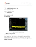
Fig. 4-22 Side Lobe Ratio Shown by the Marker
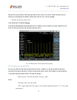
e) Measure the pulse width, which is equal to the reciprocal of the frequency difference between the peaks of two
side lobe envelopes.
Press [Maker], [Delta], [Peak], [Next Pk Right] and [Next Pk Right].
In this case, the reciprocal of the frequency difference indicated by the differential marker is the pulse width, as
shown in Fig. 4-23. To obtain the most accurate pulse width, you can manually adjust the marker location and
measure the distance between the zero crossing points of two adjacent side lobes. You can also reduce the
resolution bandwidth to make the zero crossing point sharper and measurement accuracy higher.
Содержание S3302A
Страница 1: ...S3302 Series Handheld Spectrum Analyzer Datasheet Saluki Technology Inc...
Страница 70: ...Tel 886 2 2175 2930 Email sales salukitec com www salukitec com 70...
Страница 125: ...Tel 886 2 2175 2930 Email sales salukitec com www salukitec com 125 Fig 7 1 FM Demodulation Analysis Results...
Страница 139: ...Tel 886 2 2175 2930 Email sales salukitec com www salukitec com 139 Fig 8 3 Schematic Diagram of List Scanner...


