37
2.
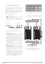
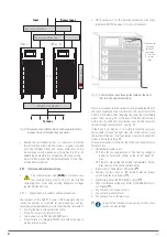
Supply voltage to the external manual bypass
panel
Observe the wiring diagrams of the external manual by-
pass panels shown in Fig. 40. It shows the two possible
options, with a single AC input network or with sepa-
rate networks for the rectifier and the separate bypass.
3.
Turn on the circuit breakers of the manual bypass
panel in the following order: Output, Input and
Bypass [equipment version B, with separate by-
pass line].
Turn on the circuit breaker of the static bypass
of the back of the sub-rack [models with 2 and
4 slots].
The LCD touch screen starts up. The rectifier indicator
flashes during start-up. The rectifier enters the normal
operating state and after around 20 seconds the recti-
fier indicator stops flashing red to remain permanently
active in green. After initialization, the static bypass re-
mains active, supplying voltage to the output terminals
from the AC network with its green bypass indicator.
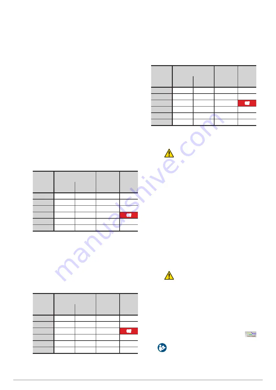
Tab. 9 shows the colour and status of the LEDs at the
end of the actions in step 3, as well as the parity of
the bypass and monitoring module and power module
indications.
Led
Number of LEDs in bypass
and monitoring module of:
Number
of LEDs
in power
module
Colour
2 and 4
slots
6 slots
Rectifier
NO
YES
YES
Green
Batteries
NO
YES
YES
Red
Bypass
NO
YES
NO
Green
Inverter
NO
YES
YES
Off
Output
NO
YES
NO
Green
Status
YES
YES
YES
Red
Tab. 9.
Status indications with inverter off.
4.
The inverter starts automatically.
The inverter in-
dicator flashes during start-up in red colour. After ap-
proximately 1 minute, the inverter is operating and the
output on the bypass is transferred to the inverter. The
bypass led switches is turned off and the inverter led
turns to green. The UPS is operating in Normal Mode.
Tab. 10 shows the status of the LEDs.
Led
Number of LEDs in bypass
and monitoring module of:
Number
of LEDs
in power
module
Colour
2 and 4
slots
6 slots
Rectifier
NO
YES
YES
Green
Batteries
NO
YES
YES
Red
Bypass
NO
YES
NO
Off
Inverter
NO
YES
YES
Green
Output
NO
YES
NO
Green
Status
YES
YES
YES
Red
Tab. 10.
Status indications with inverter running.
5.
Turn on the protection or circuit breaker of bat-
teries.
The red led of the batteries is turned off a
few minutes later and then turns green. They will be
charged by the equipment charger. Tab. 11 shows the
status of the LEDs.
Led
Number of LEDs in bypass
and monitoring module of:
Number
of LEDs
in power
module
Colour
2 and 4
slots
6 slots
Rectifier
NO
YES
YES
Green
Batteries
NO
YES
YES
Green
Bypass
NO
YES
NO
Off
Inverter
NO
YES
YES
Green
Output
NO
YES
NO
Green
Status
YES
YES
YES
Green
Tab. 11.
State indications in normal mode and charging
batteries.
Information regarding LED indications:
–
The MBS for sub-racks of 2 and 4 slots has one led
and the sub-racks of 6 slots has six leds.
Both have a graphical synoptic of six indicators and
can be viewed when accessing the "System" screen
menu, see chapter 7.
–
All power modules have a synoptic of four LEDs,
replicated in the diagram of the bypass and moni-
toring module for equipment with 6 slots.
The MBS LEDs reflect the status and behaviour of the
complete sub-rack system and the LEDs of the module
reflect the individual status and behavior of each of
them.
In general in 6-slot equipments and for normal op-
erations or operating mode changes, any alteration
of status in an MBS led is reproduced in its module or
power modules counterpart, but not necessarily in re-
verse. In addition, any action or incident on an MP will
be reflected on the MBS screen.
The LEDs can be displayed in three states, off, on or
flashing and in green or red when it is two-colour.
Consider that if the UPS is shutdown for over
temperature, overload or other cause, it will re-
start automatically when the reason for it ends and
therefore the alarm signal disappears.
6.3. TRANSFER PROCEDURES BETWEEN OPERATING
MODES.
6.3.1. Transfer from Normal Mode to Bypass Mode.
•
From the main menu at the bottom of the touch screen, click
on the "Operation" drop-down icon and on the icon
to switch to Bypass Mode.
NOTE:
In Bypass Mode, the load is fed directly from
the mains instead of the direct output voltage of the
inverter. The connected loads are exposed to the incidents
of the commercial AC grid.
EMi3
SERVOMOTOR VOLTAGE STABILISER
USER'S MANUAL

