46
SALICRU
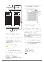
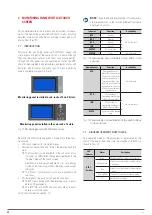
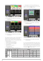
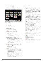
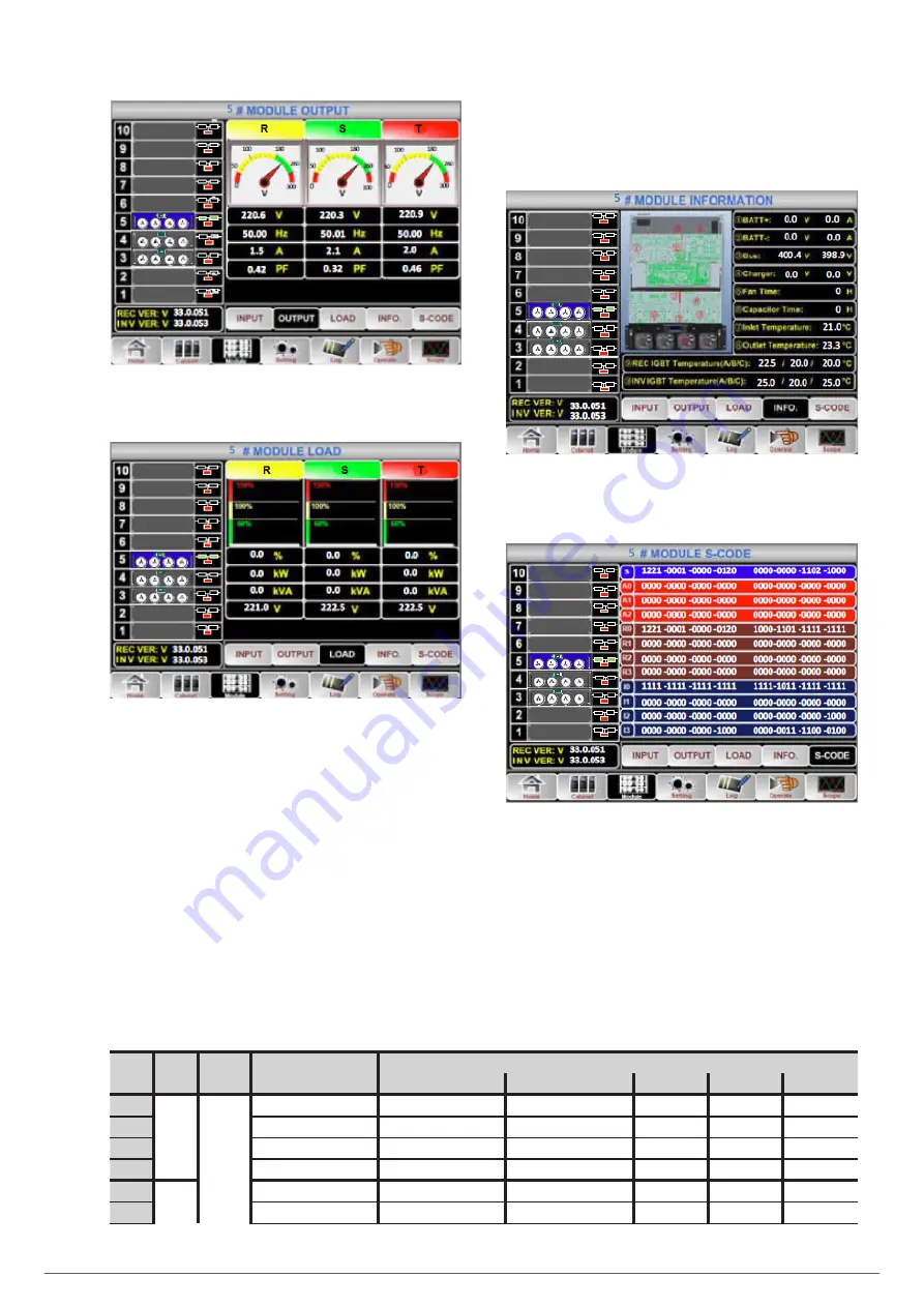
Fig. 50.
Information menu of the module or power modules.
Output sub-menu.
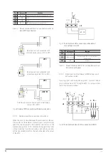
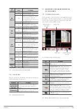
Fig. 51.
Information menu of the module or power modules.
Load sub-menu.
The information in the Load sub-menu includes the load per-
centage, the active load and the apparent load, see Fig 51.
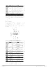
There are two other sub-menus, those for information and S-
Code. The first one provides the following information meas-
ured by each module:
•
Battery voltage [positive and negative].
•
Battery currents [positive and negative].
•
DC bus voltages [positive and negative].
•
Fan operating time.
•
Operating time of DC capacitors.
•
Inlet air temperature.
•
Air temperature exhausting.
•
Three temperatures of the rectifier IGBT [three-phase].
•
Three temperatures of the inverter IGBT [three-phase].
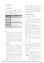
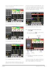
The second, the S-Code, shows the event codes for each power
module. It is useful for the
T.S.S.
, see Fig 53.
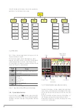
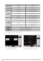
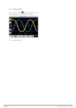
Fig. 52.
Information menu of the module or power modules.
Information sub-menu.
Fig. 53.
Information menu of the module or power modules.
S-Code sub-menu.
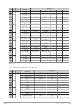
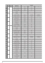
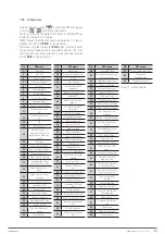
Tab. 18 shows the meaning between the bits and the status of
the [S-Code] module and Tab. 19 shows the meaning between
the bits and the module's alarm [A-Code]. The information in
the R Code and the I-Code refers to special rectifier and inverter
status bits and the interpretation of their meaning is exclusively
restricted to our
T.S.S.
or to the distributor.
32 BIT
4 BIT
Module
INFORMATION
LOG VALUES
0
1
2
4
8
1
1
Load status
None
UPS
BYP
Another module
2
REC Status
Off
Soft start-up
Normal work
3
INV status
Off
Soft start-up
Normal work
4
BYP status
Out of range
Correct for supply
5
Status of batteries
Not connected
Increase
Floating
Discharge
Not operational
6
Reserved

