38
SALICRU
6.3.2. Transfer from Bypass Mode to Normal Mode.
•
From the main menu at the bottom of the touch screen, click
on the "Operation" drop-down icon and on the icon
to switch to Normal Mode. After the inverter is started, the
UPS will switch to Normal Mode.
6.4. OPERATIONS OF THE MANUAL BYPASS SWITCH
(MAINTENANCE).
6.4.1. Procedure to switch from Normal Mode to
Maintenance Bypass Mode.
•
This procedure is applicable to transfer the load power
supply from the inverter output [Normal Mode] to the
manual bypass switch [Maintenance Bypass Mode].
Before performing this operation, read the LCD
panel messages to ensure that the bypass power
supply is stable [equipment input voltage] and that the in-
verter is synchronized with the bypass voltage. This is im-
portant to avoid the risk of breaking the power supply to the
load.
1.
Click on the icon
in the "Operation" menu. The "In-
verter" indicator on the diagram will flash green and the
"Status" indicator will turn red. In addition, the acoustic
alarm will be activated. The load will be transferred to the
static bypass and the inverter will be set to Standby.
NOTE:
To silence the acoustic alarm click on the icon
in
the "Operation" menu. This action cancels the acoustic
alarm, but does not delete the warning message on the
screen, which disappears when the alarm condition
ends.
2.
Remove the mechanical lock of the manual bypass switch
from the external panel and turn it to "On". The load will be
fed directly from the mains via the manual bypass.
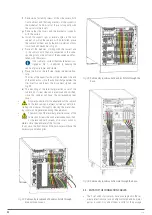
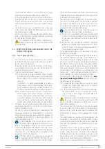
When a protection panel is provided instead of a manual
bypass panel, the mechanical lock of the manual bypass
switch in the back of the sub-rack must be removed manu-
ally and turned "On" as this switch will not be available in
the panel. It is recommended in this operating mode [By-
pass mode] and condition [manual bypass panel defect] to
perform the following actions:
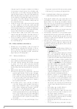
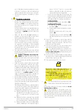
Remove the fixing screws of the side trim profiles.
Remove the fixing screws of all PMs and MBS.
Slightly pull the handles at the ends in each one of
them until you remove them 4-5 cm from the socket,
to remove them from the connector on the backplane
of the equipment.
Before any change of operating mode and after car-
rying out the possible corrective actions, it is neces-
sary to correctly insert the modules into their original
position and fix them with their screws.
3.
Switch the protection or the battery circuit breaker of the
battery cabinet to "Off" position.
4.
Switch the circuit breakers of the manual bypass panel to
the “Off” position in the following order: Output, Input and
Bypass [equipment version B, with separate bypass line].
5.
Initiate timely maintenance tasks.
NOTE:
To remove a faulty module it is not necessary to
switch the device to "Bypass Mode", since a power
module can be removed while the system is in op-
eration. It is recommended to check that the power
of the load does not exceed the residual operating
modules and to stop the power module by means of
the "On/Off" button located next to the LED indica-
tions of the synoptic on its front. Use an object of
diameter ≤ 3 mm, such as a small screwdriver, to in-
sert it into the hole indicated as “ ” and press for
around 5-6 seconds on the button located inside.
•
Wait for around 10 minutes for the DC bus capacitor
set is fully discharged before removing a module.
•
Maintenance operations are restricted to
T.S.S.
personnel or the distributor. Under no circumstances
can there be access to inside of the equipment, beyond the
connection actions, which are also reserved exclusively for
qualified
personnel.
Do not open the subrack or modules, there is a high risk of
electric shock that can be deadly.
•
When the UPS is operating in "Manual Bypass
Mode” (maintenance or repairing period), the con-
nected equipment is not protected against power outages
or blackouts, overvoltages, voltage and/or frequency fluc-
tuations, ... when fed directly from the commercial AC grid.
6.4.2. Procedure to switch from Maintenance Bypass
Mode to Normal Mode.
1.
Reset all the modules of the system when they have been
extracted as indicated in point 2 of the previous section
6.4.1. Insert and fix them.
2.
Turn on the circuit breakers of the manual bypass panel
in the following order: Bypass [equipment version B, with
separate bypass line], Input and Output.
The LCD touch screen starts up. The rectifier indicator
flashes during its start-up. The rectifier enters the normal
operating state and after around 20 seconds the rectifier
indicator stops flashing red to remain permanently active
in green. After initialization, the static bypass remains ac-
tive, supplying voltage to the output terminals from the AC
mains and the bypass indicator turns green. Check this last
point on the diagram and/or the LCD before proceeding.
3.
Turn the manual bypass switch on the external panel to
"Off" and set the mechanical lock back.
In installations with protection panels [without manual by-
pass switch], turn the manual bypass switch on the sub-
rack to "Off" and place its mechanical lock.
It is necessary for safety to place the mechanical
blocking of the switch, otherwise there is a risk of
improper operation of the switch at any time, with the con-
sequent destruction of the UPS and load.
4.
After around 60 seconds approximately, the UPS transfers
the load on the inverter. Switch the protection or the battery
circuit breaker of the battery cabinet to the "On" position.

