32
SALICRU
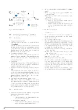
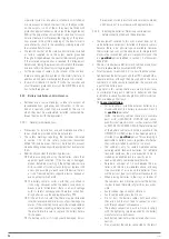
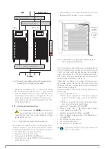
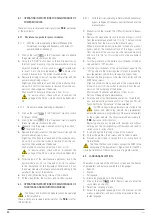
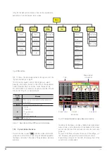
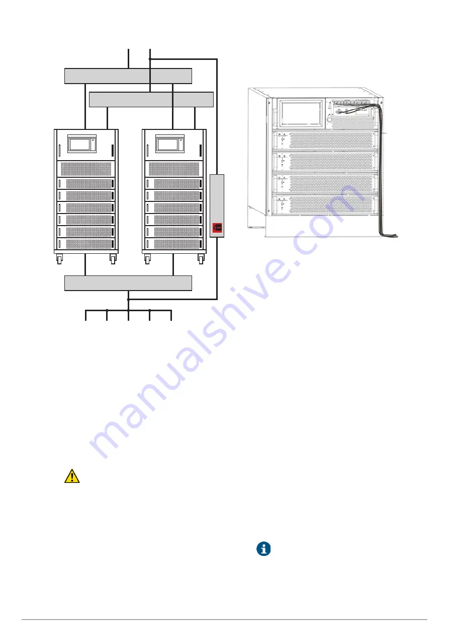
Output circuit breaker
Manual Bypass
UPS no. 1
UPS no. 'N'
Input
To loads
•••
Bypass circuit breakers
Input circuit breakers
Bypass Input
Fig. 30.
Example of parallel system, with separate static
bypass line and manual bypass panel.
•
Beyond the communication bus, it is necessary to provide
the installation with parallel systems, a panel provided
with the individual input and output protections and a
manual bypass with mechanical locking. See Fig. 29 or 30
depending on whether or not separate static bypass line.
For more information see the documentation for the "Rec-
ommended installation".
5.5.7. Interface and communications.
•
The communications line
(COM)
constitutes a very
low voltage safety circuit and must be installed
separately from other lines carrying dangerous voltages
(power distribution line).
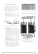
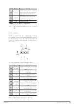
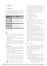
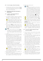
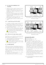
5.5.7.1. Digital inputs, dry contacts and communications.
The subracks of the ADAPT X series UPS incorporate the fol-
lowing connections as standard for communication with ex-
ternal equipment peripherals or with other identical equipment:
•
Four digital inputs through terminal strip.
•
Three dry contacts via terminal strip.
•
Communication via RS232 and RS485 ports .
•
Pre-installation to integrate SNMP card without having to
modify internal wiring.
•
DB15 connectors for the parallel connection with other
identical ADAPT X devices. Only in 6-slot subracks.
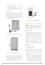
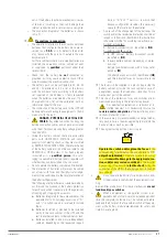
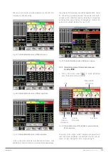
Cables passed
through the
decorative
side channel
in 2-slot and
4-slot sub-
racks
Fig. 31.
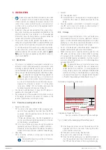
Control cables pass through the inside of the front
trim in 2-slot and 4-slot models.
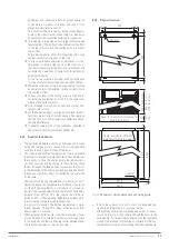
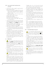
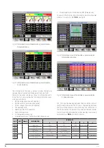
All communications related connectors are grouped together on
the control panel and are accessible from the same front for the
2 and 4 slot models after removing the cover that completely
covers them - see Fig. 29- or the back of the device for models
with 6 slots in which only a protective cover has the communi-
cations through terminal block - see Fig. 30-.
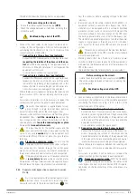
In the 2 and 4 slot models, it is possible to route the communi-
cation cables through the right side trim of the subrack, since
the profile of the part itself generates a natural channel that
makes it possible, see Fig. 28.
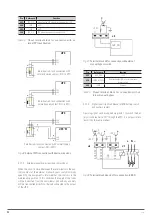
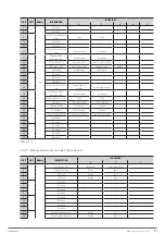
The communication module has the following connections via
terminal block:
•
Temperature probes input.
Probe for the compensation of the floating voltage of
batteries. Parameter shown on the control panel dis-
play.
Probe for measuring the ambient temperature. Param-
eter shown on the control panel display.
•
Signal input of the external EPO button
(*)
.
•
Auxiliary contact input of the external manual bypass
switch (maintenance bypass)
(*)
.
•
Signal trip input of the BCB battery switch
(*)
.
•
Shunt trip release voltage controller of the BCB battery cir-
cuit breaker
(*)
.
•
Dry contacts, static bypass alarm
•
Dry contacts, general alarm.
•
Dry contacts, mains failure alarm
(*)
In option the mechanisms necessary for their inter-
action can be provided.

