


24
SALICRU
f.
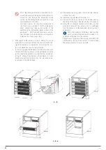
Remove the fastening screws of the side covers, both
front and rear and the fixing brackets of the sockets in
the models of 2 and 4 slots or the set of supports with
the castors in the 6 slots.
g.
Remove the side covers and the brackets or supports
with the castors.
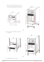
h.
Install the support rails or lateral angles in the rack
cabinet on which the subrack will be installed, place
the subrack on them and fix them. A simulation of how
it will look will be shown in Fig. 23.
i.
Place all the modules, starting with the lowest one
in the subrack until they are connected to the corre-
sponding slot on the bottom of the backplane and fas-
tened with the screws.
In any subracks system the module below is as-
signed as No. 1, in addition to keeping the
centre of gravity lower and stable.
j.
Place the trim on the left side, facing the device fron-
tally.
The trim of the opposite side will be placed at the end
of the connection, since the channel that generates the
trim itself is used to pass the dry contact signals, see
Fig. 28.
k.
The mounting of the terminal protection cover of the
subrack on its rear side can be removed and omitted,
since the cabinet will have the corresponding rear
cover.
•
Any mechanization for the adaptation of the subrack
in the rack cabinet is always carried out before in-
stalling the modules, thoroughly cleaning the metal shav-
ings that may be generated during the operations.
•
The mounting of the terminal protection cover of the
subrack on its rear side can be removed and omitted,
as the rack cabinet by means of its covers will com-
pletely close the perimeter of the first one.
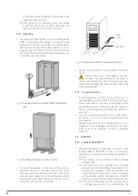
In any case, the front door and the back cover will have the
necessary ventilation grids.
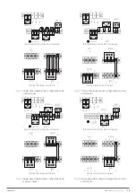
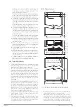
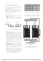
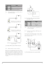
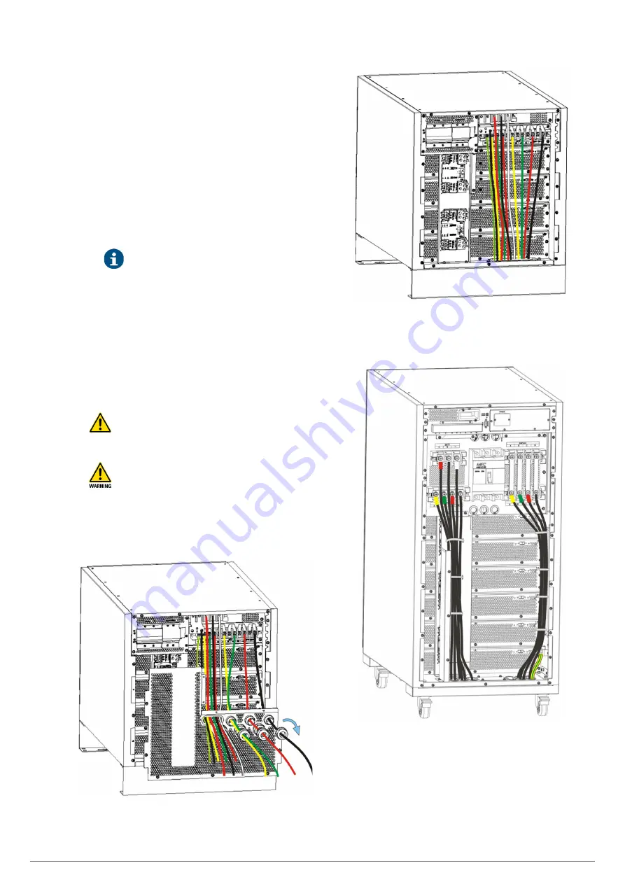
Fig. 24.
Cable entry in subrack of 2 and/or 4 slots through
means in rear cover.
Fig. 25.
Cable entry in subrack of 2 and/or 4 slots through the
base.
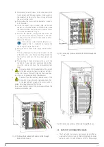
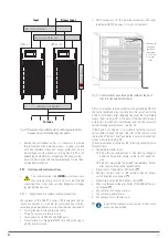
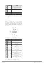
Fig. 26.
Cable entry in subrack of 6 slots through the base.
5.3. ENTRY OF THE CONNECTION CABLES.
•
The 2-slot and 4-slot subracks have a cable gland in the ter-
minal protection cover and an elliptical hole behind a metal
part as a cover. Any one of them is valid for the passage


