2
SALICRU
General index
1. INTRODUCTION.
1.1. THANK-YOU LETTER.
2. SAFETY INFORMATION.
2.1. USING THIS MANUAL.
2.1.1. Conventions and symbols used.
2.1.2. Safety considerations.
3. QUALITY ASSURANCE AND STANDARDS.
3.1. STATEMENT BY THE MANAGEMENT.
3.2. STANDARDS.
3.2.1. First and second environment.
3.2.1.1. First environment.
3.2.1.2. Second environment.
3.3. ENVIRONMENT.
4. PRESENTATION.
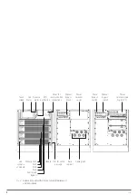
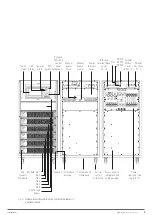
4.1. VIEWS.
4.1.1. Views of the subracks.
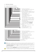
4.2. DEFINITION OF THE PRODUCT.
4.2.1. Subrack and battery module nomenclatures.
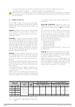
4.3. GENERAL DESCRIPTION.
4.3.1. Introduction.
4.3.2. Architecture.
4.3.2.1. Structural diagram.
4.3.2.2. Parallel system.
4.3.3. Operating modes.
4.3.3.1. Normal mode.
4.3.3.2. Battery mode.
4.3.3.3. Auto-start mode (automatic start).
4.3.3.4. Bypass mode.
4.3.3.5. Manual bypass mode (maintenance bypass).
4.3.3.6. Parallel-Redundant Mode.
4.3.3.7. ECO mode.
4.3.4. Battery management (factory preset settings).
4.3.4.1. Basic functions.
4.3.4.2. Advanced functions.
4.3.4.3. Protection of batteries.
5. INSTALLATION.
5.1. RECEPTION.
5.1.1. Reception, unpacking and contents.
5.1.2. Storage.
5.1.3. Unpacking.
5.1.4. Transport to the site.
5.2. LOCATION.
5.2.1. Location of the ADAPT X.
5.2.2. Room for the batteries.
5.2.3. Physical location.
5.3. ENTRY OF THE CONNECTION CABLES.
5.4. PROTECTIVE DEVICES AND CROSS SECTION OF THE
CONNECTION CABLES.
5.4.1. Input, bypass and output.
5.4.2. Battery installation and maintenance.
5.4.2.1. General recommendations.
5.4.2.2. Installing the batteries. Preliminary considerations before
connecting them and their protections.
5.4.3. Access to the interior of the subrack for its connection.
5.5. CONNECTION.
5.5.1. Connecting the device to the mains.
5.5.2. Separate static bypass line connection. In version B only.
5.5.3. Connection of the output, terminals (X6 to X9).
5.5.4. Connection of the battery terminals of the equipment with
those of the battery module.
5.5.5. Earth bonding terminal connection.
5.5.6. Parallel connection, 6-slot subracks only.
5.5.6.1. Parallel bus connection.
5.5.7. Interface and communications.
5.5.7.1. Digital inputs, dry contacts and communications.
5.5.7.2. Analogue input of battery and ambient temperature probes.
5.5.7.3. Signal input of the remote EPO button (Emergency Stop).
5.5.7.4. External manual bypass auxiliary contact input.
5.5.7.5. Signal shunt trip circuit breaker of BCB battery switch and
auxiliary contact.
5.5.7.6. Dry contacts.
6. OPERATION
6.1. INTRODUCTION.
6.2. COMMISSIONING OF THE UPS.
6.2.1. Controls before commissioning.
6.2.2. Commissioning.
6.3. TRANSFER PROCEDURES BETWEEN OPERATING MODES.
6.3.1. Transfer from Normal Mode to Bypass Mode.
6.3.2. Transfer from Bypass Mode to Normal Mode.
6.4. OPERATIONS OF THE MANUAL BYPASS SWITCH
(MAINTENANCE).

