9
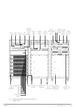
Touch
screen
Manual
bypass
switch
Interface
terminal block
cover
J2 - 10
Power
terminals (see
Fig. 6 to 11)
Power
terminal
cover
Acoustic
alarm
EPO
pushbutton
Led
Status
Manual
bypass
block
Handle
Module: No.1
No.2
No.3
No.4
No.5
No.6
Control and
Bypass
Led
synoptic
of module
Trim for cable
passage
Swivel
castors
with brake
Cable gland on
frame base
Synoptic
LEDs and
control
panel
keypad
SNMP
Slot RS232
RS485
Access cover to
cable gland and
cable passage
Parallel
bus cover
P1 - 2
Parallel
Switch
Cover
SW1 - 2
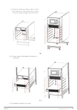
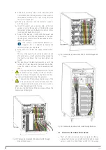
Fig. 3.
Subrack model with 6 slots, to install between 1
and 6 modules.
EMi3
SERVOMOTOR VOLTAGE STABILISER
USER'S MANUAL

