28
SALICRU
5.4.3. Access to the interior of the subrack for its
connection.
•
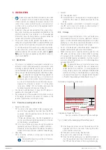
All subrack units in the SLC ADAPT X series have the fol-
lowing connection elements:
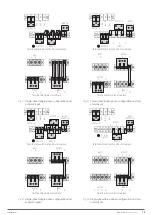
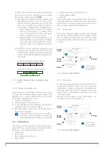
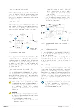
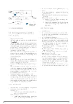
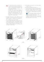
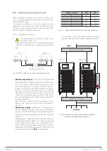
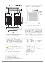
Terminal block for power. Depending on the type of the
input and output, some terminal strips are supplied be-
tween terminals to obtain the required configuration
(see Fig. 6, 7 and 8).
Separate terminal block connectors for digital inputs
and dry contacts signals.
Terminal block connector for RS485.
DB9 connector for RS232.
Slot ready to integrate the SNMP card.
The 6-slot subracks also have HDB15 / DB15 connec-
tors for the parallel bus.
•
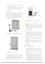
All power connection terminals (input, output and batteries)
are located on the back of the subracks, behind a protective
cover. Only
T.S.S.
personnel or
qualified
personnel are au-
thorized to remove these covers for connection.
Do not remove more covers than indicated. Access to other
internal parts is reserved exclusively for
T.S.S.
•
The dry contacts connectors are arranged in:
2-slot and 4-slot subracks. On the front of the UPS, be-
hind the metal cover located next to the control panel.
6-slot subracks. On the back of the UPS, behind a metal
protective cover.
•
Consider the cross section of the cables and crimped termi-
nals at their ends, in relation to the surface and size of the
terminals, to obtain optimum contact between them.
•
At the end of the wiring tasks, the equipment must be
fitted with the corresponding covers firmly attached. This
includes the right lateral frontal profile, used as a channel
for the passage of the interface cables and related at the
point ‘
j.
’ of section 5.2.3.
5.5. CONNECTION.
•
The connection of the equipment can only be carried
out by
qualified
personnel with the help of the sup-
plied documentation, however the first commissioning of
the system is reserved exclusively to our
T.S.S.
or distrib-
utor, as an implicit action that activates the start of the
guarantee of the product .
Do not apply power to the equipment before the first com-
missioning.
•
This equipment is suitable for installation in networks with
power distribution system TT, TN-S, TN-C or IT, taking into
account at the time of installation the particularities of the
system used and the national electrical regulation of the
destination country.
•
In equipment with three-phase input will feed the
system with 4 wires (3 phases and Neutral), being
essential the neutral in the power of all three-phase
system.
Optionally we can supply an isolation transformer to gen-
erate the neutral, in those mains supply that do not have it.
Only in single-phase equipments and in compliance with
the nominal supply voltage of the equipment, it is possible
to dispense with the neutral and to replace it with another
phase in its absence. In this case and in equipment with
independent bypass line, as in any equipment, respect the
rotation of the phases when connecting the input and by-
pass, using the same pair of phases in both inputs.
•
In equipments with three-phase input connected to an IT-
type power distribution system, breakers, differentials and
circuit breaker protections must cut the NEUTRAL in addi-
tion to the three phases.
•
All the connections of the equipment including the control
ones will be done with all the switches at rest position
and with no power supply (power supply line switch of the
equipment in «Off» position).
•
Do not connect ADAPT X devices in parallel with different
firmware versions, settings and/or back-up times. Follow
all instructions for connecting up to 5 subracks in parallel
(6-slot subracks only).
•
The tightening torques of the screw terminals are as fol-
lows:
For screw with M6 thread, tightening torque of 5Nm.
For screw with M8 thread, tightening torque of 13Nm.
For screw with M10 thread, tightening torque of 25Nm.
•
The parallel connection of 6-slot subracks will be carried
out as described in sections 5.5.1 to 5.5.5 and for each one
of them, and is subject to having its manual bypass panel
for both the installation procedure, start-up and future
maintenance.
5.5.1. Connecting the device to the mains.
•
As it is an equipment with protection against class I
electrical shock, it is essential to install the protec-
tive earth conductor to the terminal identified as
. Con-
nect this conductor before supplying voltage to the input
terminals.
•
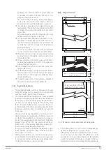
In accordance with the safety standard EN-IEC 62040-1,
in equipments without independent bypass line, the in-
stallation must be equipped with an automatic backfeed
protection system, such as a contactor, which prevents the
occurrence voltage or hazardous energy on the UPS input
line during a mains failure.
The standard is applicable regardless of whether the power
supply is single-phase or three-phase, and for individual
units of subracks as well as for each of the UPS subracks of
a parallel system.
All values are calculated for a
maximum total cable
length of 30 m
between the distribution board, equipment
and loads.
•
There can be no derivation of the line from the Back-
feed protection to the UPS, since the safety standard
will not be complied with.
•
Warning labels shall be affixed to all primary power
switches installed in areas remote from the equipment to
alert electrical maintenance personnel of the presence of a
UPS in the circuit.


