7
4. PRESENTATION.
4.1. VIEWS.
4.1.1. Views of the subracks.
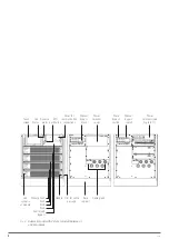
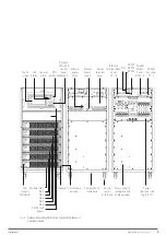
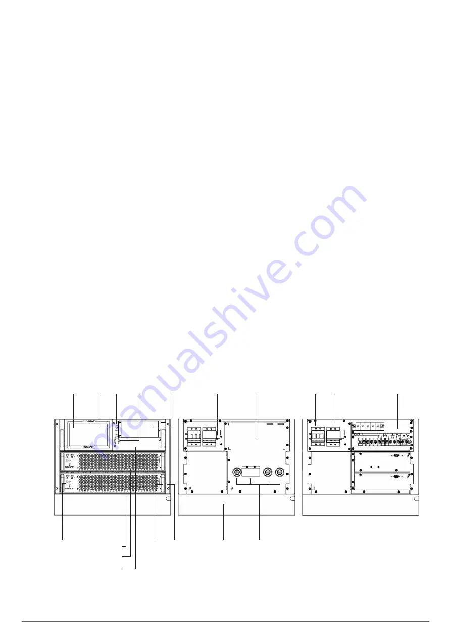
The illustrations in Fig. 1 to 3 are represented with the max-
imum of modules installed in each subrack, although the unit
may differ mainly due to the number of integrated modules de-
pending on the required power.
Basically the operation and technical specifications are the
same, except for the indicated power.
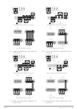
The copper rods placed between the connection terminals that
can be seen in the illustrations Fig. 1 to 3, correspond to equip-
ment with three-phase input and output, with a common input
for the rectifier and the static bypass. Fig. 6 to 11 shows all
possible input and output configurations.
The subracks incorporate a control panel with 7” colour touch
screen as an interface between the equipment and the end-
user, which provides different information through menus struc-
tured in categories (see section 7).
In the system of subracks connected in parallel, each one has
its own control panel through which the individual parameters
can be checked.
Touch
screen
Static
bypass
switch
Manual
bypass
switch
Cover for
communication
connections
Power
terminals (see
Fig. 6 to 11)
Power
terminal
cover
Acoustic
alarm
EPO
pushbutton
Led
Status
Manual
bypass
block
Handle
Module: No.1
No.2
Control and
Bypass
Led
synoptic
of module
Trim cables
Base
support
Cable gland
Fig. 1.
Subrack model with 2 slots, to install 1 or 2
modules.
EMi3
SERVOMOTOR VOLTAGE STABILISER
USER'S MANUAL

