13
4.3.2.1.1. Power modules -PM-.
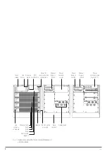
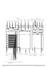
The power modules are the basic core of the SLC ADAPT X
system. Apart from the static bypass block and the LCD touch
screen, each power module contains all the converters and
functionalities of a traditional UPS. Since this equipment is
structured by a number of variable modules depending on the
subrack used, a multi-parallel system is obtained with the be-
haviour equivalent to the stand alone UPS and the advantages
of a modular UPS.
The system supplies power to the critical load (such as com-
munication and data processing equipment) with uninterrupted
high quality AC power. The power supplied by the unit is stable,
without voltage and/or frequency variations and free from
other disturbances such as power outages or blackouts, sine
wave flucutations, electrical noise, anomalies commonly pre-
sent in the commercial AC grid.
This is achieved through the double-conversion high frequency
Pulse Width Modulation -PWM-, in combination with a digital
control based on a Digital Signal Processor -DSP-, which pro-
vides high reliability and availability.
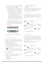
As it can be seen in Fig. 4, the AC power supplied to the UPS
input is converted to DC voltage. This voltage supplies a con-
verter that transforms the voltage type from DC to AC, clean
of disturbances and variations of the AC input mains. In case
it fails, the PFC-Rectifier changes the input source of the AC
network to the batteries, feeding similarly through the output
of the UPS to the load for a limited time, the back-up time is
determined by the battery set.
4.3.2.1.2. Static Bypass.
Static transfer switch.
In case of inverter failure, overload or overtemperature, the
voltage connected to the static bypass line can supply power
to the load connected to the UPS output.
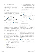
The Static Bypass Module identified in Fig. 4 contains the
power management and control circuits that allow the most
optimum decision in each scenario to be made, in order to se-
lect the most favourable power to the critical load connected
to the output of the UPS, either from the inverter or from the
static bypass itself.
During normal system operation, the load is connected to the
inverter and in case of overload or fault, it will automatically
transfer to the static bypass line. In order to provide a clean
transfer (without no break) between the inverter output and
the bypass line, they must be fully synchronized during normal
operation. This is achieved through real-time digital control of
the inverter, so that the frequency of the inverter follows the
frequency of the bypass line if the bypass is within the range of
acceptable frequencies.
In addition, a Manual Bypass, which is very useful during the
periods of maintenance or fault, is included and allows contin-
uous feeding of the critical load while the UPS is out of service.
When the UPS is operating on bypass mode (over static
bypass) or manual bypass mode (maintenance or re-
pairing period), the connected loads are not protected
against power outages or blackputs, overvoltages,
voltage and/or frequency fluctuations, as they are di-
rectly fed from the commercial AC grid.
Input terminals of the UPS and Static Bypass.
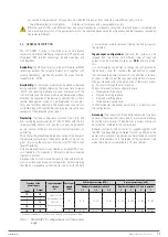
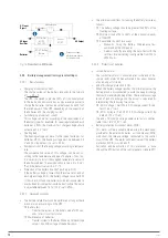
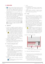
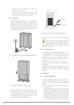
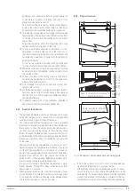
Fig. 5 shows the physical layout of the terminal block for the 2
and 4-slot subracks as well as the 6-slot subrack.
These illustrations show the connection copper rods between
the terminals of both inputs (PFC-rectifier input and static by-
pass) for a common supply, usually the most common one.
PE
Output U
Output V
Output W
Bypass R
Input R
Bypass S
Input S
Bypass T
Input T
Bypass N
Input N
Bat. +
Bat. N
Bat. –
OUTPUT N
Terminal block in 2-slot and 4-slot subrack.
BATT
+ N –
INPUT
R S T N
OUTPUT
U V W N
Terminal block in 6-slot subrack.
Fig. 5.
Terminal block for three-phase/three-phase con-
figuration and common input (PFC-rectifier and
static bypass).
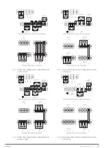
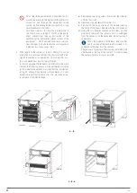
When separate AC mains are available to separately feed the
PFC-rectifier and static bypass inputs, the connection copper
rods between the phases must be removed depending on the
available subrack model -see Fig. 6-.
In this configuration, the static bypass and maintenance bypass
share the same AC source independent of the PFC-rectifier
source.
Although the ADAPT X equipment is configurable in
terms of type of input and output, any modification by
the customer or user is restricted, since in addition to
modifications in the connection copper rods, it is neces-
sary to make settings through the password-restricted
screen, exclusively reserved to
T.S.S.
or distributors.
EMi3
SERVOMOTOR VOLTAGE STABILISER
USER'S MANUAL

