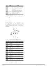
36
SALICRU
6. OPERATION
6.1. INTRODUCTION.
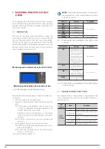
The operating modes of the SLC ADAPT X, in respect to the
nature of the output voltage, are defined in the Tab. 8. This
section describes the different procedures in each operation
mode, including transfers between them, the UPS settings and
procedures to enable the inverter to "On/Off".
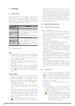
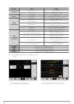
Operating modes
Description
Normal mode
The load is fed from the UPS inverter.
Bypass Mode (Static
bypass)
The load is fed from the static bypass. This mode can
be considered as a temporary transition between
normal mode and the manual bypass or a temporary
abnormal operating condition.
Note:
In this mode the load is not protected, since it is
powered directly from the AC network and therefore is
subjected to the fluctuations thereof.
Maintenance Bypass
mode (manual
Bypass switch)
The load is powered directly from the AC network
through the manual bypass switch, scheduled for
periods of maintenance or repairing.
Note:
In this mode the load is not protected, since it is
powered directly from the AC network and therefore is
subjected to the fluctuations thereof.
Tab. 8.
Operating modes.
Note:
•
During the description of the user manual the term bypass
and control module, bypass and monitoring module or MBS
is used to refer to the same sub-rack. The same applies to
the power module term or PM.
•
See section 7 [Description of the control panel], for eve-
rything related to the functionality of the buttons and the
touch screen.
•
There are some parameters that can modify the operation
of the UPS described in this section. These parameters are
set at the factory settings and later only modifiable by our
staff of
T.S.S.
or by the distributor to be password pro-
tected.
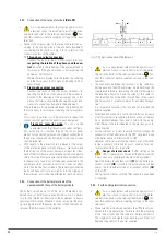
Power switches.
•
The sub-rack system of 2 and 4 slots incorporates two
switches, circuit breakers, one for the input bypass line and
the other for the manual bypass or maintenance line, which
by default is mechanically secured to prevent wrong ma-
noeuvrings. All other transfers are processed automatically
using internal control logics.
Instead, the 6-slot sub-rack system has only the manual by-
pass circuit breaker, which by default is also mechanically
locked.
•
In any case, the installation must have an external panel
with the circuit breaker for input, output, a static bypass
if applicable and a manual bypass. The protection size
will be of the current adjusted to the installed power, un-
less a short-term extension is foreseen, in which it can be
adapted to this one.
The "Recommended installation" document sup-
plied with the user manual defines the protection
size, their selectivity, the number of poles according to the
input/output configuration and the cross cable section of
each line. This information is a reference guide and the
user is ultimately responsible for checking and applying the
necessary corrective factors according to the installation
itself and the local or national regulations or standards.
In the same documentation, the information is also avail-
able for the parallel sub-racks of 6 slots, shown as a mere
example in Figs. 29 and 30.
6.2. COMMISSIONING OF THE UPS.
6.2.1. Controls before commissioning.
Before starting the device:
•
Check that all connections have been made properly and
with sufficient tightening torque, respecting the labelling of
the equipment and the instructions of section 5.
•
Check that the static bypass switch on the sub-rack, the
module or battery modules and the protection panel are in
the "Off" position.
•
Make sure that all loads are "Off".
•
It is very important to proceed in the established order.
•
Refer to Fig. 1 to 3 for parts of the equipment.
•
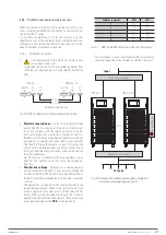
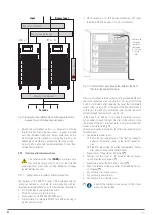
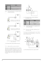
Fig. 29 and 30 show a manual bypass panel for parallel
system of “N” equipments, with common AC line and with
independent inputs for rectifier and bypass. In both, the in-
stallation will match the number of protections to the avail-
able parallel sub-rack.
Although the internal and external manual bypass switches
have the same functionality, the latter one has a higher per-
formance because it allows complete isolation of the equip-
ment during periods of preventive maintenance, repairing or
replacement.
The following sections describe all the steps to be per-
formed considering the availability of a manual bypass
panel, although for a single sub-rack it may be a protection
panel [same panel but without the manual bypass mecha-
nism].
6.2.2. Commissioning.
•
The first commissioning of the equipment or a parallel
system is reserved for authorized personnel, whether
T.S.S.
or a distributor. This operation activates the start of
the product warranty and among other jobs a test and cali-
bration at site of the equipment is also started, but which is
not described in this document.
•
Follow this procedure to start the UPS from a total shut-
down position.
Proceed as follows:
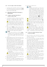
1.
Check the rotation of the phases and neutral to the
input of the equipment, as well as the static bypass
line when it is available. Correct in the case of wrong
connection or phase rotation.
During the next manoeuvres described in this
section, the output terminals of the UPS will be
alive at any moment. If any loads are connected
to them, check that it is reliable to apply
voltage, otherwise disconnect it securely from
the output terminals of the UPS.

