39
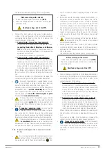
6.5. EPO PUSH BUTTON (EMERGENCY STOP).
PROCEDURE.
•
Conceptually the EPO push button is designed to disconnect
the UPS in emergency conditions (e.g. fire, flood, etc.).
The device has an EPO push button and the user can install
an external one, connected to the equipment via the com-
munication terminal J4.
•
Press the EPO push button, the system stops immediately
the rectifier, the inverter and the bypass, and consequently
breaks the power supply to the load. Batteries are no longer
charged or discharged.
If the AC input mains is present, the UPS control circuit will
remain active, but without voltage at the output.
•
To completely isolate the UPS, follow the steps in the next
section.
6.5.1. Complete shutdown of the UPS, with EPO.
1.
If a shutdown is planned or scheduled, stop the loads be-
forehand. In case of emergency, go directly to step 2.
2.
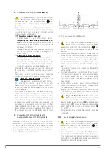
Press the EPO button on the bypass and monitoring module.
3.
Turn the protection or the battery circuit breaker of the bat-
tery cabinet to the "Off" position.
4.
Turn the circuit breakers of the manual bypass panel to the
“Off” position in the following order: Bypass [equipment
version B, with separate bypass line], Input and Output.
The EPO condition will be cleared when the input
panel switch is turned "Off".
The UPS is completely out of service.
6.5.2. UPS restart after complete shutdown with EPO.
The procedure is used to restore the system after the EPO has
been activated and its complete shutdown:
1.
Once you press the EPO button, you need to end the proce-
dure before attempting to restart the system.
2.
Restart the UPS as described in section 6.2.2.
The EPO condition will disappear when the input
switch indicated in the previous section is turned
off, since the alarm will be cleared.
6.6. AUTOMATIC RESTART.
When the UPS is operating in Normal Mode and the input mains
fails, it will automatically switch to Batteries Mode, where the
loads are fed from the inverter from the energy stored in the
batteries. If the mains fault goes on beyond the possible power
that the battery set can supply, the end of discharge is reached
and the UPS will stop.
The UPS will restart automatically by supplying output voltage:
1.
After returning the commercial AC grid.
2.
If the parameter "Automatic reset" after EOD is enabled.
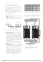
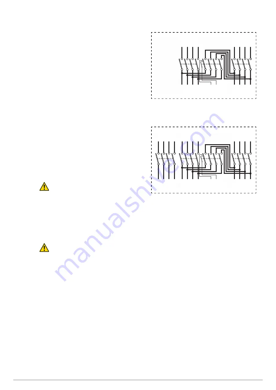
Functionality of the switches:
Input circuit breaker.
Static bypass circuit breaker - line 2.
Output circuit breaker.
Manual bypass circuit breaker -maintenance Bypass-.
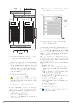
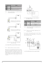
It is necessary to connect the auxiliary contact of the
manual bypass switch on the external panel, with the J5
terminal block of the communication block of the UPS as a
preventive action. In case of wrong or untimely switching
of the manual bypass switch to "On" with the equipment in
"Normal Mode", this auxiliary contact will force the transfer
of the equipment to "Bypass Mode". In this way avoiding a
short circuit and the destructive consequences that can be
associated with same.
If you are purchasing a manual bypass panel, you must en-
sure that you have the auxiliary contact normally open -NO-
which should be advanced to the closed position.
In parallel systems the manual bypass mechanism will have
as many auxiliary contacts as parallel units there are for
their separate connection.
UPS input
mains
UPS
output
Input line
To loads
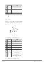
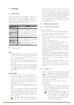
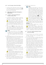
External manual bypass panel, with common inputs for
rectifier and static bypass.
To the UPS J5
terminal block
External manual bypass panel with separate inputs for
rectifier and static bypass.
UPS input
mains
UPS
bypass
input
UPS
output
AC1 line
input
AC2 line
input
To loads
To the UPS J5
terminal block
Fig. 40.
Internal wiring diagram of an external manual bypass
panel for a device.
EMi3
SERVOMOTOR VOLTAGE STABILISER
USER'S MANUAL

