31
5.5.6. Parallel connection, 6-slot subracks only.
When we talk about parallel in this section we refer to sub-
racks, since the parallelization of modules is a characteristic of
the entire ADAPT series.
It is possible to parallel up to a total of 5 subracks of 6 slots
regardless or not of the number of them installed in each one,
although it is advisable to be uniform numerically, this will de-
pend on the level of redundancy required.
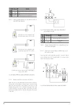
5.5.6.1. Parallel bus connection.
•
The communications line -COM- constitutes a very
low voltage safety circuit.
To preserve the quality must be installed separately from
other lines carrying dangerous voltages (power distribution
line).
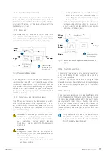
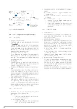
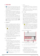
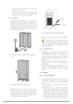
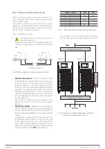
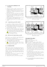
Parallel connection bus
UPS no. 1
•••
•••
SW2
P1
P2
SW1
UPS No. 'N'
SW2
P1
P2
SW1
OFF
ON
OFF
ON
Fig. 28.
DB15 connectors on the communication bus.
•
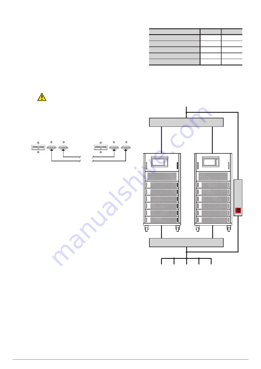
Parallel connection bus
. Use the 15-wire signal shielded
bundle and DB15 connectors at the ends to attach a max-
imum of 5 subracks with the sequence shown in Fig. 28.
Each cable bundle has a male and a female connector at
the ends, which must be connected between two correlative
equipments. It is imperative to close the bus loop in parallel.
The length of the parallel cable is about 1.5 meters and
should not be prolonged under any circumstances due to
the risk of interferences and failures in the communication
that this would entail.
Fig. 28 shows an installation with two equipments in par-
allel. For five, operate similarly to close the communica-
tions bus.
•
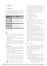
Parallel bus settings
. Although up to five equipments
can be connected in parallel, it is necessary to change the
position of the "Mini DIP Switch” SW1 and SW2 located on
the back of the device, depending on the number of parallel
subracks.
The equipment is shipped from the factory adjusted to the
requested requirements. When it is necessary to modify the
initial configuration in number of units, the position of SW1
and/or SW2 must be changed according to Tab. 2 and by
application by PC inform each equipment. These actions are
exclusively reserved for the
T.S.S.
or the distributor.
Subracks in parallel
SW1
SW2
1
OFF
OFF
2
ON
OFF
3
OFF
OFF
4
OFF
OFF
5
OFF
OFF
Tabla 2.
SW1 and SW2 selection, units parallel system.
To access them it is necessary to remove the corresponding
cover that keeps them from tampering and then reinsert it.
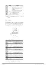
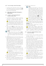
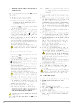
Input circuit breaker
Output circuit breaker
Manual Bypass
UPS no. 1
UPS No. 'N'
Input
To loads
•••
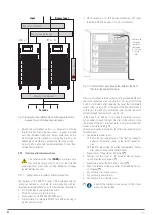
Fig. 29.
Example of parallel system, with a single AC
network and manual bypass panel.
EMi3
SERVOMOTOR VOLTAGE STABILISER
USER'S MANUAL

