54
SALICRU
8. OPTIONAL
8.1. INSTALL AN SNMP DRIVE.
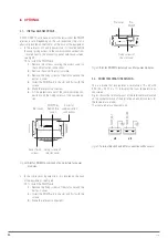
All SLC ADAPT X units have a slot for the inclusion of the SNMP
electronic card. Depending on the sub-rack model, the slot is
physically located on the front or on the back of the equipment.
•
In the sub-racks of 2 and 4 power slots, it is located behind
the cover giving access to the communication connections
, located next to the monitoring panel with touch screen,
see Fig 59 .
To install the SNMP card:
1.
Remove the screws securing the access cover to
the communication connections.
2.
Remove the cover. The slot is visible.
3.
Remove the fixing screws of the slot cover and the
part as a cover.
4.
Install the SNMP card in the slot and fix it with the
screws.
5.
Make the relevant connections.
6.
Fit the protective cover of the communication con-
nections and the fixing screws of the communica-
tion.
Cover fixing
screws
Cover for
communication
connections
Slot cover
Fixing screws of
the slot cover
SNMP Slot
behind the
cover
Fig. 59.
Slot for SNMP in sub-rack of 2 and 4 slots for power
modules.
•
In the sub-racks of 6 power slots, it is located on the back
of the equipment, see Fig 60 .
To install the SNMP card:
1.
Remove the fixing screws of the slot cover and the
part as a cover.
2.
Install the SNMP card in the slot and fix it with the
screws.
3.
Make the relevant connections.
Slot cover
Fixing screws of
the slot cover
Slot
SNMP
Fig. 60.
Slot for SNMP in 6-slot sub-rack for power modules.
8.2. ROOM TEMPERATURE SENSOR.
This is a probe that incorporates a resistance of R = 5k with
B25 / 50 = 3275 K ± 1% to display the room temperature on
the screen.
Fig. 61 shows the terminal pinout of the terminal block located
on the connector block of the digital inputs and dry contacts for
the temperature probes.
The room probe is connected to J3.
J2
J3
TEMP_BAT
TEMP_ROOM
Fig. 61.
Terminal block J2 and J3 for connection with sensors.

