


Video Input Setup
Video sources come into the switcher through the input
BNCs. Depending on how you want to use these video
sources, or where they come from, you may want the
switcher to pair them together, or associate an external
device with them. Pairing two video sources together is
usually used for an auto select key where an external
device, such as a character generator, outputs both a key
video and key alpha. Associating a video source with an
external device allows special control over that device
to become active when you select the source on a bus.
Input Sources
Video inputs coming into the switcher are assigned the
video format that they are coming into the switcher in,
and the type of device they are coming from. Assigning
a video format allows SmartConversion to identify the
conversion loop required to convert this video input.
Assigning a device type allows you to associate a device
you are controlling from the switcher with an input.
Note:
Refer to the documentation that came with your Evertz
®
IP Input for information on setting up video inputs.
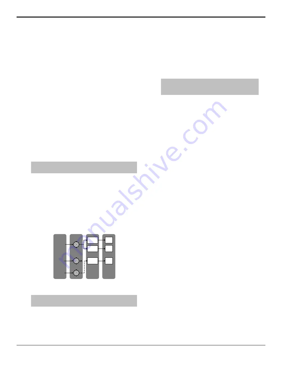
Each input BNC on the switcher can have one or multiple
input sources assigned to it. This can allow configurations
such as multiple device control or device redundancy.
For example, to access both the CG and clip functionality
of your graphics processor you can assign two input
sources, one set up as a CG and the other as a video
server, to the physical BNC from the device. You can
then use two source buttons to access the different
functionalities of the same device.
In 005
(CG)
In 006
(Video Serv.)
Physical
BNC
External
Device
Input
Source
Bus
Map
CG
1
VID
1
In 015
(RoboCam)
CAM
1
Cam 1
(offline)
Graphics
Processor
Cam 2
To Set Up Video Sources
Tip:
You can see if there is a valid video signal on an input BNC
from the Input Status menu.
1.
Press
HOME
>
Setup
>
Installation
>
Source
Configuration
>
Input Type
.
2.
Use the
Input
knob to select the input source that
you want to configure.
3.
Use the
Physical BNC
knob to select the physical
BNC that you want to assign the input source to.
Physical BNCs that appear gray are on Video Inputs
boards that are not installed.
4.
In the
Input Type
area, select how you want the
input source configured. Input types are assigned to
the input sources, and not the physical BNC.
Note:
All input sources must be assigned to Video or
Alpha unless the device connected to that input source is
controlled by the switcher.
•
Alpha
— alpha signal to be paired with a fill,
or video, signal for an auto select key.
•
Char Gen
— video signal from a character
generator.
•
Off
— no video signal, or to temporarily turn an
input off.
•
Robotic Cam
— video signal from a robotic
camera.
•
Router
— video signal from a router.
•
Video
— video signal from any source you are
not controlling from the switcher.
•
VTR
— video signal from a VTR or video
server.
5.
Use the
Video Mode
knob to select the HDR and
WCG of the input video source. If the dynamic range
and/or color gamut of the video source are different
than the those the switcher is operating in, the input
video will be converted to the values the switcher is
operating in.
•
SDR BT.601
— Standard Dynamic Range in
an SD video format. (SD default)
•
SDR BT.709
— Standard Dynamic Range in
an HD/UHDTV1 video format. (HD/UHDTV1
default)
•
HLG BT.709
— Hybrid Log Gamma in an
HD/UHDTV1 video format.
•
PQ BT.709
— Perceptual Quantizer in an
HD/UHDTV1 video format.
•
S-Log3 BT.709
— Sony
®
S-Log3 in an
HD/UHDTV1 video format.
•
SDR BT.2020
— Standard Dynamic Range
using Wide Color Gamut in an HD/UHDTV1
video format.
•
HLG BT.2020
— Hybrid Log Gamma in an
HD/UHDTV1 video format.
•
PQ BT.2020
— Perceptual Quantizer in an
HD/UHDTV1 video format.
•
S-Log3 BT.2020
— Sony
®
S-Log3 in an
HD/UHDTV1 video format.
24
• Video Input Setup — Acuity Setup Manual (v9.2)
Содержание Acuity 4410AR-020
Страница 1: ...Acuity Setup Manual v9 2...


