248
Rockwell Automation Publication 193-UM015D-EN-P - February 2015
Chapter 6
Protective Trip and Warning Functions
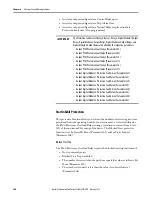
Operator Station Trip
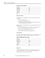
The E300 Electronic Overload Relay provides the capability to plug and play its
optional operator stations. The operator station protection feature trips the E300
Electronic Overload Relay when you press the red O (stop) button. This feature
is a failsafe mechanism to allow you to de-energize a contactor coil anytime the
red O (stop) button is pressed.
Operator Station Trip should be disabled when an operator station is being used
to send start and stop signals to an automation control system.
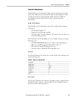
The E300 Electronic Overload Relay trips with an operator station trip
indication if:
•
No trip currently exists
•
Operator Station Trip is enabled
•
You press the red O button on an operator station
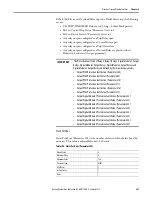
If the E300 Electronic Overload Relay trips on an operator station trip, the
following occurs:
•
The TRIP/WARN LED flashes a red 3-long / 4-short blink pattern
•
Bit 3 in Control Trip Status (Parameter 7) sets to 1
•
Bit 0 in Device Status 0 (Parameter 20) sets to 1
•
Any relay outputs configured as a Trip Relay open
•
Any relay outputs configured as a Control Relay open
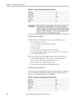
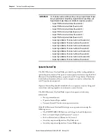
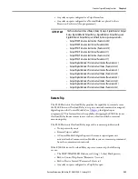
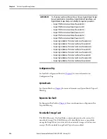
IMPORTANT
The Protection Fault State of Relay 0, Relay 1, Relay 2, Digital Module 1 Output
Relays, Digital Module 2 Output Relays, Digital Module 3 Output Relays, and
Digital Module 4 Output Relays are defined by the respective parameters:
•
Output PT00 Protection Fault Action (Parameter 304)
•
Output PT00 Protection Fault Value (Parameter 305)
•
Output PT01 Protection Fault Action (Parameter 310)
•
Output PT01 Protection Fault Value (Parameter 311)
•
Output PT02 Protection Fault Action (Parameter 316)
•
Output PT02 Protection Fault Value (Parameter 317)
•
Output Digital Module 1 Protection Fault Action (Parameter 322)
•
Output Digital Module 1 Protection Fault Value (Parameter 323)
•
Output Digital Module 2 Protection Fault Action (Parameter 328)
•
Output Digital Module 2 Protection Fault Value (Parameter 329)
•
Output Digital Module 3 Protection Fault Action (Parameter 334)
•
Output Digital Module 3 Protection Fault Value (Parameter 335)
•
Output Digital Module 4 Protection Fault Action (Parameter 340)
•
Output Digital Module 4 Protection Fault Value (Parameter 342)
Содержание Allen-Bradley E300
Страница 1: ...E300 Electronic Overload Relay Bul 193 592 User Manual...
Страница 124: ...124 Rockwell Automation Publication 193 UM015D EN P February 2015 Chapter 4 System Operation and Configuration Notes...
Страница 128: ...128 Rockwell Automation Publication 193 UM015D EN P February 2015 Chapter 5 Operating Modes...
Страница 292: ...292 Rockwell Automation Publication 193 UM015D EN P February 2015 Chapter 6 Protective Trip and Warning Functions...
Страница 304: ...304 Rockwell Automation Publication 193 UM015D EN P February 2015 Chapter 7 Commands Notes...
Страница 372: ...372 Rockwell Automation Publication 193 UM015D EN P February 2015 Chapter 8 Metering and Diagnostics...
Страница 460: ...460 Rockwell Automation Publication 193 UM015D EN P February 2015 Appendix A Specifications Notes...
Страница 501: ...Rockwell Automation Publication 193 UM015D EN P February 2015 501 Parameter List AppendixB Notes...
Страница 502: ...502 Rockwell Automation Publication193 UM015D EN P November 2013 Appendix B Parameter List...
Страница 545: ......


