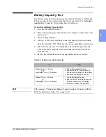
M3500B/M5500B Service Manual
2
-
27
Diagnostic Tests
2
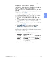
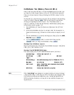
Defibrillator Test (AC Power At 200 J)
These instructions describe how to test the defibrillation function when pow-
ered only by the AC Power Module (no battery installed).
This test is required only if the defibrillator is connected to AC power during
normal use.
If all results are as described, the unit passes the test. Return to the main Diag-
nostic Test menu by pressing
.
If there is any failure, begin troubleshooting and repairing the unit as needed.
See "Troubleshooting" on page 3-1 and Table 3-9 "Operational Problems -
Defibrillation and Synchronized Cardioversion" on page 3-22.
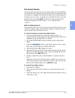
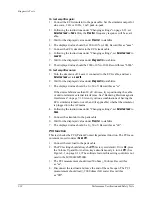
1. Turn defibrillator off and remove the battery. Connect the AC Power
Module.
2. Connect the defibrillator analyzer to the pads cable. Set the analyzer to
measure delivered energy. If needed, reset the analyzer’s display to
read 0.
3. Turn the defibrillator on, and from the Diagnostic Menu, Select the
Defib
Meas Test
and press
.
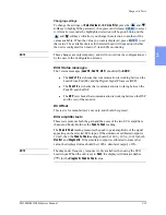
4. Use the
softkey to select 200J. Then press the
softkey to charge the defibrillator. Press
.
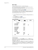
Readings from defibrillator analyzer:
Read the delivered energy indicated by the defibrillator analyzer. It should be
200J +15% (+30J). Record as "aaa".
Readings from M3500B/M5500B display:
The results displayed by the M3500B/M5500B should be as follows:
Available Energy:
Not recorded - failure if >0.
ms to Charge:
<15000
(Record as "bbbbb")
Delivered Energy:
Actual delivered energy ("aaa") +7%(Record as "ccc")
Impedance:
42 to 57 ohms
(Record as "dd")
Peak Current:
Ignore. Derived from same measurements as delivered
energy and impedance
Defib Errors:
Not recorded - failure if any reported.
MAIN
ENTER
ENERGY SELECT
CHARGE
SHOCK
Содержание Heartstart XLT
Страница 1: ...H E A R T S TA R T X LT S e r v i c e M a n u a l M 3 5 0 0 B M 5 5 0 0 B ...
Страница 2: ......
Страница 3: ...Service Manual M3500B HeartStart XLT M5500B Heartstart 4000 Defibrillator Monitor ...
Страница 6: ......
Страница 16: ......
Страница 20: ......
Страница 52: ......
Страница 110: ...Opening the Sealed Case 4 24 Removal and Replacement Figure 4 13 Battery Connector Location 4 Pin Battery Connector ...
Страница 195: ...M3500B M5500B Service Manual 6 17 System Functional Descriptions 6 Figure 6 3 Power Distribution and Fusing ...
Страница 205: ...M3500B M5500B Service Manual 7 9 Waveforms 150J continued 7 Waveforms 150J continued 150J 75 ohms 150J 100 ohms ...
Страница 206: ...Waveforms 150J continued 7 10 Specifications Waveforms 150J continued 150J 125 ohms 2ms div 150J 125 ohms 5 ms div ...
Страница 208: ...Waveforms 200J continued 7 12 Specifications Waveforms 200J continued 200J 75ohms 200J 100ohms ...
Страница 216: ......
Страница 223: ......
Страница 224: ...M3500 90900 Printed in USA February 2003 Second Edition M3500 90900 2 ...

