Specifications
7
-
2
Specifications
Charge Time:
Less than 3 seconds to 200 Joules with a new, fully charged
M3516A SLA battery pack at 25
o
C. Less than 15 seconds to 200 Joules when
powered by a M3517A or M3518A power module with no battery installed.
Patient Impedance Range:
25 to 180 Ohm.
Manual Mode
Manual Output Energy (Delivered)
: 5, 10, 25, 50, 70, 100, 150, 200 Joules.
Controls:
On/Energy Select, Off, Charge/Disarm, Shock, ECG Lead Select,
SpO
2
, HR Alarms, Exit Manual Mode, Sync, Pacer Start/Stop, Pacer Rate,
Pacer Current, Pacer Mode, Display Contrast, ECG Gain, Volume, Print Strip,
Print Summary, Annotated Mark Event.
Indicators:
LCD display for ECG waveform and text prompts, Audio alerts,
QRS Beeper, Charging Tone, Charge Done Tone, Manual Mode LED, Sync
LED, Pacer LED, Printer.
Armed Indicators:
Charge done tone and available energy indicated on dis-
play.
Energy Selection:
Front Panel "1" key.
Charge Control:
Front Panel "2" key.
Shock Control:
Front Panel "3" key.
Synchronizer:
SYNC message appears on the monitor and is annotated on
the printer (if printing while in Sync Mode). An audible beep sounds with
each detected R-wave, while a tick mark on the monitor and printed strip indi-
cate the discharge points. Synchronizer delay is less than 60 msec from peak
R-wave to peak current of the defibrillation discharge.
Table 7-1 Delivered Energy vs. Load Impedance
Selected
Energy
(J)
Delivered Energy (J)
Accuracy
Load Impedance (ohms)
25
50
100
125
150
5
4.7
5
5.2
5.4
5.2
+ 2 J
10
9.3
10
10.4
10.7
10.4
+ 2 J
25
23.4
25
26.2
26.9
26.2
+ 4 J
50
46.7
50
52.3
53.5
52.1
+15%
70
65.4
70
73.1
75.0
72.9
+15%
100
93.5
100
104.7
107.2
104.4
+15%
150
140.3
150
156.8
161.0
156.5
+15%
200
187
200
209.3
214.6
208.6
+15%
Содержание Heartstart XLT
Страница 1: ...H E A R T S TA R T X LT S e r v i c e M a n u a l M 3 5 0 0 B M 5 5 0 0 B ...
Страница 2: ......
Страница 3: ...Service Manual M3500B HeartStart XLT M5500B Heartstart 4000 Defibrillator Monitor ...
Страница 6: ......
Страница 16: ......
Страница 20: ......
Страница 52: ......
Страница 110: ...Opening the Sealed Case 4 24 Removal and Replacement Figure 4 13 Battery Connector Location 4 Pin Battery Connector ...
Страница 195: ...M3500B M5500B Service Manual 6 17 System Functional Descriptions 6 Figure 6 3 Power Distribution and Fusing ...
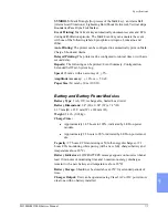
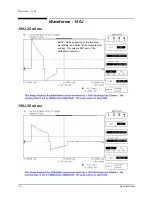
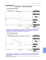
Страница 205: ...M3500B M5500B Service Manual 7 9 Waveforms 150J continued 7 Waveforms 150J continued 150J 75 ohms 150J 100 ohms ...
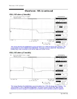
Страница 206: ...Waveforms 150J continued 7 10 Specifications Waveforms 150J continued 150J 125 ohms 2ms div 150J 125 ohms 5 ms div ...
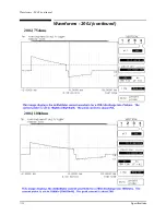
Страница 208: ...Waveforms 200J continued 7 12 Specifications Waveforms 200J continued 200J 75ohms 200J 100ohms ...
Страница 216: ......
Страница 223: ......
Страница 224: ...M3500 90900 Printed in USA February 2003 Second Edition M3500 90900 2 ...


