M3500B/M5500B Service Manual
4
-
63
Bottom Case Assemblies
4
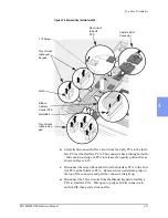
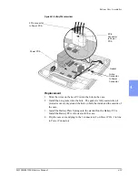
Figure 4-33 Disconnecting the Power PCA
Replacement
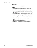
1. Place the new Power PCA into position in the case. Replace the 6 T10
screws and tighten.
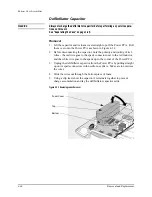
1. Replace and reconnect the defibrillator capacitor. See "Defibrillator
Capacitor" on page 4-60.
2. Reconnect the 3 connectors from the Patient Connector (2 individual
High Voltage, 1 multipin).
3. Reconnect the 2 connectors from the Battery PCA.
4. Reconnect the 1 connector from the Power Connector.
5. Reconnect the large ribbon cable to the Control PCA. Replace and relatch
the metal bail.
2 Pin Connector to
Battery PCA
4 Pin Connector to
Battery PCA
High Voltage Spade
Connectors (2)
9 Pin Connector
Patient Connector
Power Connector
(hidden)
Large Ribbon Cable
Содержание Heartstart XLT
Страница 1: ...H E A R T S TA R T X LT S e r v i c e M a n u a l M 3 5 0 0 B M 5 5 0 0 B ...
Страница 2: ......
Страница 3: ...Service Manual M3500B HeartStart XLT M5500B Heartstart 4000 Defibrillator Monitor ...
Страница 6: ......
Страница 16: ......
Страница 20: ......
Страница 52: ......
Страница 110: ...Opening the Sealed Case 4 24 Removal and Replacement Figure 4 13 Battery Connector Location 4 Pin Battery Connector ...
Страница 195: ...M3500B M5500B Service Manual 6 17 System Functional Descriptions 6 Figure 6 3 Power Distribution and Fusing ...
Страница 205: ...M3500B M5500B Service Manual 7 9 Waveforms 150J continued 7 Waveforms 150J continued 150J 75 ohms 150J 100 ohms ...
Страница 206: ...Waveforms 150J continued 7 10 Specifications Waveforms 150J continued 150J 125 ohms 2ms div 150J 125 ohms 5 ms div ...
Страница 208: ...Waveforms 200J continued 7 12 Specifications Waveforms 200J continued 200J 75ohms 200J 100ohms ...
Страница 216: ......
Страница 223: ......
Страница 224: ...M3500 90900 Printed in USA February 2003 Second Edition M3500 90900 2 ...


