M3500B/M5500B Service Manual
4
-
29
Identifying Internal Subassemblies
4
Identifying Internal Subassemblies
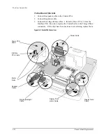
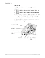
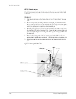
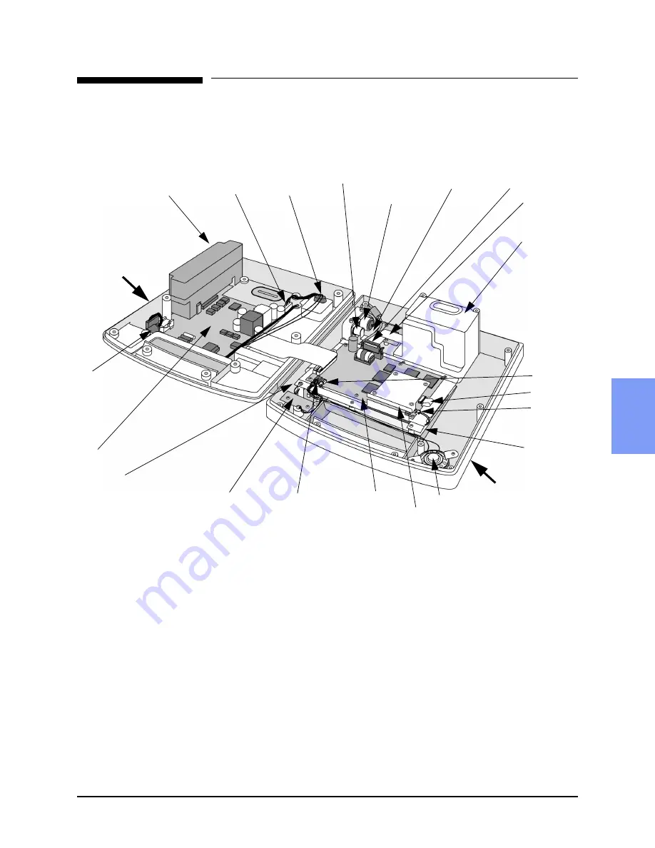
Refer to Figure 4-17 to identify the internal subassemblies.
Figure 4-17 Internal Subassemblies
Speaker
Control PCA
Interface PCA
(under Control Stack)
Display
cables -
backlight
data
thermistor
Display
(on back of
Control
Stack)
SpO
2
connector
Printer
connector
Speaker
connector
IRDA break-off
PCA
Data card receptacle
Power PCA
Defibrillator
capacitor (inside
foam shell)
Battery
connector
Pads
connector
Battery
PCA cable
Printer
bucket
(Printer on
other side
of case)
Printer
cable
ECG connector
BOTTOM
CASE
TOP CASE
SpO
2
PCA
Содержание Heartstart XLT
Страница 1: ...H E A R T S TA R T X LT S e r v i c e M a n u a l M 3 5 0 0 B M 5 5 0 0 B ...
Страница 2: ......
Страница 3: ...Service Manual M3500B HeartStart XLT M5500B Heartstart 4000 Defibrillator Monitor ...
Страница 6: ......
Страница 16: ......
Страница 20: ......
Страница 52: ......
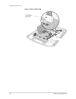
Страница 110: ...Opening the Sealed Case 4 24 Removal and Replacement Figure 4 13 Battery Connector Location 4 Pin Battery Connector ...
Страница 195: ...M3500B M5500B Service Manual 6 17 System Functional Descriptions 6 Figure 6 3 Power Distribution and Fusing ...
Страница 205: ...M3500B M5500B Service Manual 7 9 Waveforms 150J continued 7 Waveforms 150J continued 150J 75 ohms 150J 100 ohms ...
Страница 206: ...Waveforms 150J continued 7 10 Specifications Waveforms 150J continued 150J 125 ohms 2ms div 150J 125 ohms 5 ms div ...
Страница 208: ...Waveforms 200J continued 7 12 Specifications Waveforms 200J continued 200J 75ohms 200J 100ohms ...
Страница 216: ......
Страница 223: ......
Страница 224: ...M3500 90900 Printed in USA February 2003 Second Edition M3500 90900 2 ...

