M3500B/M5500B Service Manual
4
-
53
Top Case Assemblies
4
a.
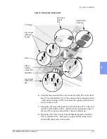
Feed the 2 flex circuits down through the slot in the case as shown in
Figure 4-28. Slide the smaller one in first, then the larger one.
b.
Peel the backing material off the new switches. Handle very carefully
and touch the adhesive as little as possible.
c.
Starting with the top edge, align the switches very carefully in their
recess in the case and roll them down slowly into place. Be careful
not to kink the flex circuit tails as you slide them into their slot under
the switches.
d.
Press firmly all over, especially the edges, to adhere the new switches
into place and seal the opening in the case.
3. Do not install the rubber overlay on the switches at this time.
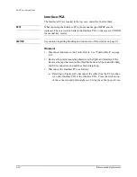
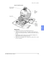
4. Replace and reconnect the Interface PCA as follows:
a.
Replace the Interface PCA into position, snapping it under the
retainer clip and replacing its screw.
b.
Guide the IRDA PCA back into position. Be careful to get the ambi-
ent light sensor into the notch in the end of the light conducting tube.
Install the 2 screws in the IRDA PCA.
c.
Replace the Manual Door shaft and rails into position. Install the 4
screws from the top side of the case into the Interface PCA and
tighten.
d.
Reconnect the 2 flex circuits from the Manual keypad to the Interface
PCA. Do not twist them.
e.
Reconnect the 3 flex circuits from the Main keypad to the Interface
PCA.
f.
Reconnect the large ribbon cable to the Control PCA and replace its
metal bail.
g.
Carefully connect the SpO
2
flex circuit to the Interface PCA.
h.
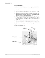
Connect ECG connector to Interface PCA, being sure ECG cable is
above SpO
2
flex circuit.
5. Reconnect the rest of the unit as follows:
a.
Replace the plastic insulating shield over the SpO
2
and Interface
PCAs. Align the hole in its wide end over the case post. Slide the left
edge of its narrow end under the lips on the metal retaining clips on
the ECG and SpO
2
connectors. Secure the shield to the clips with the
original tape, or use other plastic electrical tape.
b.
Replace and reconnect the Control Stack. See "Control Stack" on
page 4-33.
Содержание Heartstart XLT
Страница 1: ...H E A R T S TA R T X LT S e r v i c e M a n u a l M 3 5 0 0 B M 5 5 0 0 B ...
Страница 2: ......
Страница 3: ...Service Manual M3500B HeartStart XLT M5500B Heartstart 4000 Defibrillator Monitor ...
Страница 6: ......
Страница 16: ......
Страница 20: ......
Страница 52: ......
Страница 110: ...Opening the Sealed Case 4 24 Removal and Replacement Figure 4 13 Battery Connector Location 4 Pin Battery Connector ...
Страница 195: ...M3500B M5500B Service Manual 6 17 System Functional Descriptions 6 Figure 6 3 Power Distribution and Fusing ...
Страница 205: ...M3500B M5500B Service Manual 7 9 Waveforms 150J continued 7 Waveforms 150J continued 150J 75 ohms 150J 100 ohms ...
Страница 206: ...Waveforms 150J continued 7 10 Specifications Waveforms 150J continued 150J 125 ohms 2ms div 150J 125 ohms 5 ms div ...
Страница 208: ...Waveforms 200J continued 7 12 Specifications Waveforms 200J continued 200J 75ohms 200J 100ohms ...
Страница 216: ......
Страница 223: ......
Страница 224: ...M3500 90900 Printed in USA February 2003 Second Edition M3500 90900 2 ...


