M3500B/M5500B Service Manual
6
-
9
System Functional Descriptions
6
Defibrillation Functions
The following sections describe the defibrillation functions.
Charging
There are 2 events that can initiate a charging cycle:
z
In AED Mode, when the analysis algorithm determines a shock is
needed and sends a signal to another section of the Control PCA.
z
In Manual Mode, when front panel key #2 (
CHARGE
) is pressed, the
keypress is transferred from the key to the Interface PCA via a flex
circuit. The Interface PCA transfers the keypress to the Control PCA
via a large ribbon cable. The keypress is then detected and processed
by the Control PCA.
In either case, the charging cycle is initiated and controlled by the Control
PCA. It directs the Power PCA to begin charging the charge capacitor, and it
monitors the voltage on the capacitor as reported back by the Power PCA.
When the Control PCA detects that the selected energy (voltage) level has
been reached, it directs the Power PCA to stop charging. The Control PCA
then continues to monitor the voltage on the capacitor, and as the voltage
bleeds down it directs the Power PCA to top up the charge to the correct level.
Should a decision be made to change the selected energy to a lower value, the
user would scroll up through the displayed energy level choices, go past
200 J, then start scrolling up again from 5 J. At the 200 J to 5 J transition, the
Control PCA directs the Power PCA to disarm (completely discharge) the
capacitor. The user can then select the new energy level and charge normally.
If the requested charge is not used within 30 seconds, the Control PCA auto-
matically directs the Power PCA to disarm the capacitor as a safety precau-
tion.
Delivering a shock
The discharging cycle (delivering a shock) is initiated by only one event -
pressing front panel key #3 (
SHOCK
). This keypress is transferred from the
key to the Interface PCA via a flex circuit. The Interface PCA transfers the
keypress to the Control PCA via a large ribbon cable. The keypress is then
detected and processed by the Control PCA.
The Control PCA directs the Power PCA to deliver the shock. Patient resis-
tance is derived from the current and voltage delivered during the initial por-
tions of the waveform, and the biphasic waveform is then adjusted as needed
to deliver the correct energy.
The Power PCA will abort delivery of the shock if any of the following
occurs:
z
During the impedance measurement, the impedance is outside of
operating limits (too high or too low).
Содержание Heartstart XLT
Страница 1: ...H E A R T S TA R T X LT S e r v i c e M a n u a l M 3 5 0 0 B M 5 5 0 0 B ...
Страница 2: ......
Страница 3: ...Service Manual M3500B HeartStart XLT M5500B Heartstart 4000 Defibrillator Monitor ...
Страница 6: ......
Страница 16: ......
Страница 20: ......
Страница 52: ......
Страница 110: ...Opening the Sealed Case 4 24 Removal and Replacement Figure 4 13 Battery Connector Location 4 Pin Battery Connector ...
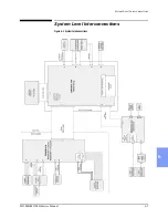
Страница 195: ...M3500B M5500B Service Manual 6 17 System Functional Descriptions 6 Figure 6 3 Power Distribution and Fusing ...
Страница 205: ...M3500B M5500B Service Manual 7 9 Waveforms 150J continued 7 Waveforms 150J continued 150J 75 ohms 150J 100 ohms ...
Страница 206: ...Waveforms 150J continued 7 10 Specifications Waveforms 150J continued 150J 125 ohms 2ms div 150J 125 ohms 5 ms div ...
Страница 208: ...Waveforms 200J continued 7 12 Specifications Waveforms 200J continued 200J 75ohms 200J 100ohms ...
Страница 216: ......
Страница 223: ......
Страница 224: ...M3500 90900 Printed in USA February 2003 Second Edition M3500 90900 2 ...


