Bottom Case Assembly
4
-
66
Removal and Replacement
Bottom Case Assembly
The bottom case assembly consists of the plastic case, with the Data Card
Door, Battery Cover, and Battery Eject Latch mechanism all pre installed at
the factory. The bottom case must be replaced only when there is damage to
the case itself; everything else in the bottom case is individually replaceable.
Parts to be moved from old bottom case to new
The following subassemblies must be removed from the old top case and
installed into the new one. Follow the Removal and Replacement instructions
in this chapter for each subassembly. Remove them in the order shown, and
replace them in reverse order.
1. Battery PCA, spring, cable (see"Battery PCA" on page 4-58).
2. Battery eject spring (see "Battery PCA" on page 4-58).
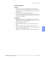
3. Patient Connector, cables, hardware (see "Patient Connector" on page 4-
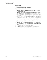
4. Power Connector, cables, hardware (see "Power Connector" on page 4-
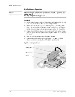
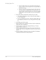
5. Defibrillator capacitor (see "Defibrillator Capacitor" on page 4-60).
6. Power PCA and shield (see "Power PCA" on page 4-62).
7. Battery.
8. All screws.
New parts to be installed - must be ordered separately
In addition, the following parts cannot be reused from the old case, and must
be ordered separately and installed into the new bottom case:
z
Case Label Set
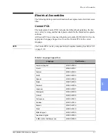
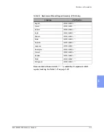
These are available in all the supported languages. See the
"Replacement Parts" chapter,
Table 5-12 to select the correct
language.
z
Primary Label
When replacing the bottom case, the Primary Label containing the
unit’s serial number must also be replaced. Be prepared to provide
information identifying the unit when ordering the bottom case.
NOTE
To enable device tracking as mandated by US Federal law, the Primary Label
must be applied before placing the unit back into service.
Содержание Heartstart XLT
Страница 1: ...H E A R T S TA R T X LT S e r v i c e M a n u a l M 3 5 0 0 B M 5 5 0 0 B ...
Страница 2: ......
Страница 3: ...Service Manual M3500B HeartStart XLT M5500B Heartstart 4000 Defibrillator Monitor ...
Страница 6: ......
Страница 16: ......
Страница 20: ......
Страница 52: ......
Страница 110: ...Opening the Sealed Case 4 24 Removal and Replacement Figure 4 13 Battery Connector Location 4 Pin Battery Connector ...
Страница 195: ...M3500B M5500B Service Manual 6 17 System Functional Descriptions 6 Figure 6 3 Power Distribution and Fusing ...
Страница 205: ...M3500B M5500B Service Manual 7 9 Waveforms 150J continued 7 Waveforms 150J continued 150J 75 ohms 150J 100 ohms ...
Страница 206: ...Waveforms 150J continued 7 10 Specifications Waveforms 150J continued 150J 125 ohms 2ms div 150J 125 ohms 5 ms div ...
Страница 208: ...Waveforms 200J continued 7 12 Specifications Waveforms 200J continued 200J 75ohms 200J 100ohms ...
Страница 216: ......
Страница 223: ......
Страница 224: ...M3500 90900 Printed in USA February 2003 Second Edition M3500 90900 2 ...

