Diagnostic Tests
2
-
16
Performance Verification and Safety Tests
Diagnostic Tests
The M3500B/M5500B includes an extensive set of diagnostic tests, which
test the major hardware components of the defibrillator.
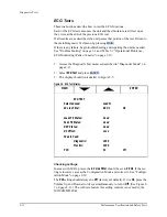
The System Log
These instructions describe how to print the system log, which includes the
unit’s serial number, hardware configuration, and a listing of error codes. The
System Log should be printed each time a Performance Verification Test is
run.
1. Enter Diagnostic Mode as described in "Diagnostic Mode" on page 2-11.
2. Select
Print Log
and press
.
3. The printer will print the System Log strip.
4. Check the printout to verify the printed results are consistent with the
hardware in place. Check options installed (SpO
2
, pacing) and the unit’s
serial number (on the bottom of the case). If the printout is not correct,
investigate and resolve the source of the mismatch. Then reset the hard-
ware options and serial number as needed using the Support Software
Tool. See "The Language Support Tool" on page 4-67.
5. If there are errors reported in the System Log:
a.
Check the time and date stamps to see if they are recent errors or not.
Consult Table 3-2 "Error Codes" on page 3-11 to identify the errors.
Then begin troubleshooting as needed (see the "Troubleshooting"
chapter.)
b.
Check that the time and date are correct. If they are not correct, access
Configuration Mode and reset them.(If there are no errors, the time
and date are not displayed.) See "Configuration Mode" on page 2-10.
Figure 2-2 Sample System Log Printout
ENTER
SYSTEM LOG
Firmware Versions
Error Codes
Main:
34
90007 18:33 19 Jan 2000
DSP:
02
196:
57.00
Key:
06
SpO2:
02.42 01.04
Language:
English
Serial Number:
US01000241
Options:
Pacer SpO2
Shocks:
2
Содержание Heartstart XLT
Страница 1: ...H E A R T S TA R T X LT S e r v i c e M a n u a l M 3 5 0 0 B M 5 5 0 0 B ...
Страница 2: ......
Страница 3: ...Service Manual M3500B HeartStart XLT M5500B Heartstart 4000 Defibrillator Monitor ...
Страница 6: ......
Страница 16: ......
Страница 20: ......
Страница 52: ......
Страница 110: ...Opening the Sealed Case 4 24 Removal and Replacement Figure 4 13 Battery Connector Location 4 Pin Battery Connector ...
Страница 195: ...M3500B M5500B Service Manual 6 17 System Functional Descriptions 6 Figure 6 3 Power Distribution and Fusing ...
Страница 205: ...M3500B M5500B Service Manual 7 9 Waveforms 150J continued 7 Waveforms 150J continued 150J 75 ohms 150J 100 ohms ...
Страница 206: ...Waveforms 150J continued 7 10 Specifications Waveforms 150J continued 150J 125 ohms 2ms div 150J 125 ohms 5 ms div ...
Страница 208: ...Waveforms 200J continued 7 12 Specifications Waveforms 200J continued 200J 75ohms 200J 100ohms ...
Страница 216: ......
Страница 223: ......
Страница 224: ...M3500 90900 Printed in USA February 2003 Second Edition M3500 90900 2 ...

