M3500B/M5500B Service Manual
2
-
23
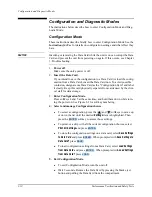
Diagnostic Tests
2
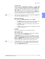
Changing settings
To change the settings of
Selected lead
or
AC Line filter
, press the
and
softkeys to highlight the parameter, then press (and release)
to select
it. After a few seconds the highlighted selection will begin to blink, and the
and
softkeys will allow you change the selection to another of the
values available. When the value you want is displayed, press
to set
that value. The available choices for Selected Lead will depend on whether
the unit is configured for 3-lead or 5-lead ECG monitoring.
NOTE
These changes are only temporary, and will not override the configuration set
by the user in the Configuration screens.
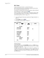
ECG Status messages
The 3 status messages (
Lead FE, Pad FE, DSP
) should all be
GOOD
.
z
The
Leads FE
test checks that communication is working between the
Leads Front End (FE) and the Digital Signal Processor (DSP).
z
The
Pads FE
test checks that communication is working between the
Pads FE and the DSP.
z
The
DSP
test checks that communication is working between the DSP
and the rest of the monitor.
DC Offset
This test is for manufacturer’s use only and should be ignored.
ECG amplifier tests
These tests measure both the gain and the noise of the two ECG amplifiers
(Leads and Pads). Both use the
Peak to Peak
reading.
The
Peak to Peak
reading measures the peak to peak amplitude of the signal
appearing on the selected ECG input. If the simulator’s calibrated output is
1.0 mV, then the
Peak to Peak
reading should be 1000 + 10% (+100) for both
Monitor
and
Diagnostic
. If the simulator output is calibrated to some other
value, the displayed value should be (1000 x simulator output) +10%.
NOTE
The diagnostic frequency response is only available when using the ECG
Leads input. When the unit is set to
Pads
, the display will indicate dashes
(
-----
) for the
Diagnostic Peak-to Peak
value.
ENTER
ENTER
Содержание Heartstart XLT
Страница 1: ...H E A R T S TA R T X LT S e r v i c e M a n u a l M 3 5 0 0 B M 5 5 0 0 B ...
Страница 2: ......
Страница 3: ...Service Manual M3500B HeartStart XLT M5500B Heartstart 4000 Defibrillator Monitor ...
Страница 6: ......
Страница 16: ......
Страница 20: ......
Страница 52: ......
Страница 110: ...Opening the Sealed Case 4 24 Removal and Replacement Figure 4 13 Battery Connector Location 4 Pin Battery Connector ...
Страница 195: ...M3500B M5500B Service Manual 6 17 System Functional Descriptions 6 Figure 6 3 Power Distribution and Fusing ...
Страница 205: ...M3500B M5500B Service Manual 7 9 Waveforms 150J continued 7 Waveforms 150J continued 150J 75 ohms 150J 100 ohms ...
Страница 206: ...Waveforms 150J continued 7 10 Specifications Waveforms 150J continued 150J 125 ohms 2ms div 150J 125 ohms 5 ms div ...
Страница 208: ...Waveforms 200J continued 7 12 Specifications Waveforms 200J continued 200J 75ohms 200J 100ohms ...
Страница 216: ......
Страница 223: ......
Страница 224: ...M3500 90900 Printed in USA February 2003 Second Edition M3500 90900 2 ...


