


-123-
Chapter 6 Description of Function Codes
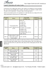
Fig.6-11
Diagram of the overcurrent stall protection function
Time(t)
Time(t)
Output current
Overcurrent stall
protective current
Output frequency (Hz)
Overcurrent anti-stall
gain is determined by F05.07
Function
code
Name
Description
(setting range)
Factory
Default
Change
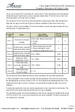
F05.09
Motor overload warning
selection
0: disabled
1: enabled
1
※
F05.09=0: no motor overload protection, it will cause motor overheat and damaged, we sug-
gest to use thermal relay.
F05.09=1: motor overload protection according to inverse time limit curve.
Function
code
Name
Description
(setting range)
Factory
Default
Change
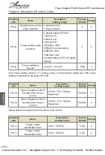
F05.10
Motor overload pre-alarm
warning detection levels
0.20
~
10.00
1.00
※
F05.11
Motor overload pre-alarm
warning detection time
50%
~
100%
80%
※
This function is used to give an early warning signal to the control system through the multi-
function output terminal before the motor overload fault protection. This warning factor is
used to determine how much warning is given before motor overload protection. The larger
the value is, the smaller the early warning is.
When the cumulative output current of the inverter is greater than the product of the overload
inverse time limit curve and F05.11, the multi-function digital multi-function output terminal of
the inverter outputs the ON signal of "motor overload pre-alarm".
C
h
a
p
te
r
6
Peaco Support FC280 Series VFD User Manual
www.peacosupport.com [email protected] Free Shipping Worldwide Reliable Supplier
PEACO SUPPORT


