background image

– 180 –

Chapter 9 Connecting to External Devices — Connection through the <USB2.0> terminal


t

To copy to a [TYPE S] storage device, one or more partitions are required. You can either format the storage device to [FAT] or perform copying after 
creating a partition through the export process.


t

To cancel the copy process, use the cursor buttons to place the cursor on [CANCEL] and press the <SET> button. On the [CANCEL] confirmation 
message that appears, select [YES] and press the <SET> button. Clips copied halfway to the copy destination are deleted.


t

If you have copied clips to a [TYPE S] storage device, you will not be able to import to that partition by card. Also, the part number display of the card 
at that instance will display [UNKNOWN].

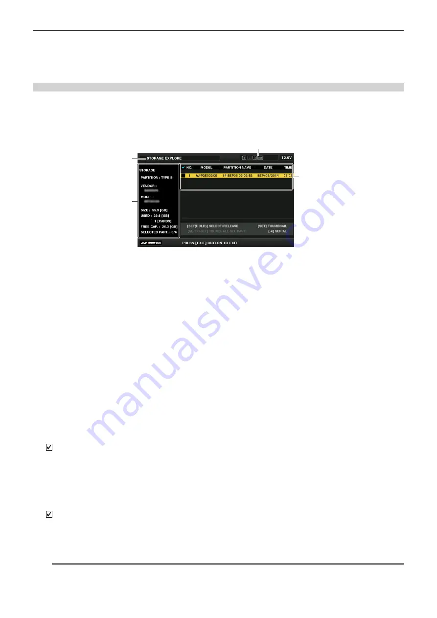
Storage device information display (explorer screen)

You can perform the following operations in the explorer screen display.


f

Storage device information display


f

Storage device partition or folder thumbnail display and selection


f

Target partition or folder selection

Explorer screen can be displayed by selecting [STORAGE] in the main menu 

 [CLIP] 

 [EXPLORE].

2

3

4

1

1  Storage device indicator

This displays the connected / not connected status and the storage device type.

Display mode

This indicates that the explorer screen of the storage device is currently displayed.

3  Device information


f

For [TYPE S] and [P2STORE] (storage devices that allow reading/writing by card)

[PARTITION]: 

[TYPE S]/[P2STORE]

[VENDOR]: 

Vendor name

[MODEL]: 

Model name

[SIZE]: 

Total capacity (unit: GB)

[USED]: 

Used capacity (unit: GB)

Used P2 card area (unit: number of clips), maximum of 23

[FREE CAP.]: 

Remaining capacity (unit: GB)

[SELECTED PART.]: 

Number of selected partition


f

For [FAT] and [OTHER] (other storage devices)

[PARTITION]: 

[FAT]/[OTHER]

[VENDOR]: 

Vendor name

[MODEL]: 

Model name

[SIZE]: 

Total capacity (unit: GB)

[FREE CAP.]: 

Remaining capacity (unit: GB)

[SELECTED PART.]: 

Number of selected folder

4  Partition or folder information


f

For [TYPE S] and [P2STORE] (partition information)

Displays a checkmark when a target partition is selected.

[NO.]: 

Partition number

[MODEL]: 

Model name of P2 card

[PARTITION NAME]: 

Name assigned to the partition

[DATE]: 

Partition record date

[TIME]: 

Partition record time

[SERIAL]: 

P2 card serial number


f

For [FAT] and [OTHER] (folder information)

Displays a checkmark when a target partition is selected.

[NO.]: 

Folder number

[FOLDER NAME]: 

Folder name (excluding the CONTENTS folder)

[DATE]: 

Folder creation date

[TIME]: 

Folder creation time

@

@

NOTE


t

For [TYPE S] storage devices, you can switch between the partition name and serial name display using the cursor buttons.


t

If there is an invalid partition in [P2STORE], the partition information is displayed in gray.

Содержание AJ-PX380G

Страница 1: ... Recorder Before using this product be sure to read Read this first pages 2 to 5 Before operating this product please read the instructions carefully and save this manual for future use ENGLISH VQT5L72A 6 E W0915HM6039 YI Model No AJ PX380G G ...

Страница 2: ...aintain adequate ventilation do not install or place this unit in a bookcase built in cabinet or any other confined space To prevent risk of fire hazard due to overheating ensure that curtains and any other materials do not obstruct the ventilation CAUTION Do not lift the unit by its handle while the tripod is attached When the tripod is attached its weight will also affect the unit s handle possi...

Страница 3: ...ion manual may cause harmful interference to radio communications Operation of this equipment in a residential area is likely to cause harmful interference in which case the user will be required to correct the interference at his own expense Warning To assure continued FCC emission limit compliance follow the attached installation instructions and the user must use only shielded interface cables ...

Страница 4: ...than the performance level required by these standards However the apparatus may be adversely affected by interference if it is being used in an EMC environment such as an area where strong electromagnetic fields are generated by the presence of signal transmission towers cellular phones etc In order to minimize the adverse effects of the interference on the apparatus in cases like this it is reco...

Страница 5: ...k the Operating Instructions accompanying the battery Back up Battery Lithium Battery For the removal of the battery for disposal at the end of its service life please consult your dealer Battery recycling symbol valid only in Taiwan r r The symbols on this product including the accessories represent the following Some symbols are not displayed on this unit ON Standby OFF d AC e DC Class II equipm...

Страница 6: ...ch as what are described below To record video in compliance with the AVC standard AVC Video To play back AVC Video that was recorded by a consumer engaged in a personal and non commercial activity To play back AVC Video that was obtained from a video provider licensed to provide the video Visit the MPEG LA LLC website http www mpegla com for details f f Use of DCF Technologies under license from ...

Страница 7: ...d compensation FBC function 66 Setting the flash band compensation function 66 Assigning functions to USER buttons 67 Selectable functions 67 Selecting audio input and adjusting recording levels 69 Selecting audio input signals 69 Adjusting the recording level 69 Selecting the F AUDIO LEVEL dial function 69 Adjusting image quality 70 Detail function 70 Skin tone function 70 RB gain control functio...

Страница 8: ...remote control mode 184 Recording and playback operations in remote control mode 184 Remote control mode menu operations 184 Remote control unit connected to the camera 184 Connecting to the extension control unit AG EC4G 186 Switch functionality in remote control mode 186 Recording and playback operations in remote control mode 186 Remote control unit connected to the camera 186 Connecting to the...

Страница 9: ...Before using the camera read this chapter Chapter 1 Overview ...

Страница 10: ...management information it will not completely erase the data on the cards When throwing these cards away or transferring them to others either physically destroy them or use a data deletion program for computers commercially available to completely erase the data Users are responsible for managing the data stored in their memory cards r r Software information about this product 1 This product incl...

Страница 11: ...o the region of use selected and automatically restart After setting up the region of use once this screen will not be displayed when subsequently turning the power on To change the region of use perform OPTION MENU AREA SETTING NOTE t t When making this setting to use the camera for the first time only the following items are changed on the camera Menu setting values other than the following item...

Страница 12: ... 12 Chapter 1 Overview Accessories Accessories Shoulder strap page 39 Mount cap already attached to the product page 16 NOTE t t After unpacking the product dispose of the packing material properly ...

Страница 13: ...ed in the Operating Instructions visit the support desk at the following website https pro av panasonic net Expanded configuration devices You can also use the following devices in addition to the basic configuration devices Part name Part No Remark Remote control cable AJ C10050G Remote control unit AJ RC10G Connecting to the remote control unit AJ RC10G page 184 Extension control unit AG EC4G Co...

Страница 14: ...This chapter describes the names functions and operations of parts on the camera Details displayed on the HOME screen of the SmartUI are also described Chapter 2 Description of parts ...

Страница 15: ...emote control unit AJ RC10G page 184 Connect the extension control unit AG EC4G optional to remote control some functions For details refer to Connecting to the extension control unit AG EC4G page 186 8 Light output terminal Connect the Ultralight 2 of Anton Bauer optional or an equivalent video light of 50 W or under The battery charge level drops sharply when the light is illuminated When using ...

Страница 16: ... description of the lens used refer to the Operating Instructions for the lens 17 Tripod mount page 39 Attach the tripod adaptor SHAN TM700 optional when mounting the camera on the tripod 18 Lens mount 1 3 type bayonet page 31 Mount the lens 19 Lens lever page 31 After mounting the lens to the lens mount tighten the lever to secure the lens 20 Mount cap page 31 Raise the lens lever to remove the c...

Страница 17: ...R CH2 FRONT VR CH3 and FRONT VR CH4 to set the controls so that this operation can be done from any input terminal 3 AUDIO IN CH1 3 AUDIO IN CH2 4 terminal page 38 Connect the audio equipment or the microphone 4 LINE MIC switch pages 38 45 Switch audio input signals connected to the AUDIO IN CH1 3 AUDIO IN CH2 4 terminal LINE Select when audio equipment is connected by the line input MIC Select wh...

Страница 18: ...n be monitored and during playback playback audio can be monitored Audio from the speaker automatically disappears when earphones are connected to the PHONES terminal 3 PHONES terminal This is the connecting terminal for audio monitor earphones stereo mini jack 4 AUDIO OUT terminal page 160 Output audio signals recorded on audio channel 1 2 or 3 4 f f Select the output signal on the AUD03 MONI scr...

Страница 19: ...der operation status and frame displays such as the area display and the counter marker and safety zone displays f f Push this towards the CHK side to display in the viewfinder the setting status for all shooting functions the list of functions assigned to the USER button etc while on stand by or while shooting Pushing it to the CHK side again while information is displayed switches the display to...

Страница 20: ...he user specified variable value by setting the main menu SW MODE W BAL PRESET or by pushing the AUTO W B BAL switch towards the AWB side and pushing the AUTO W B BAL switch towards the AWB side again while the color temperature is displayed The variable value can be set with the jog dial button page 62 A B Pushing the AUTO W B BAL switch towards the AWB side adjusts the white balance automaticall...

Страница 21: ...gnal However the sub carrier of the composite signal on the camera cannot be externally locked 4 SDI OUT2 IN terminal page 83 This is the output terminal for the SDI signal for monitor This is also the input terminal for SDI signal Switch with the main menu IN OUT SEL SDI OUT2 IN SEL Video independent from the SDI OUT1 terminal can be output Also the HD SDI signal or the down converted SD SDI sign...

Страница 22: ...display of the audio channel level meter is switched together When a screen other than the HOME screen of SmartUI is displayed the function corresponding to each setting screen is performed 17 FF button Press this button during a pause to perform fast playback Press this button during playback to perform 4x speed playback If it is pressed with playback paused the clip being played back is paused a...

Страница 23: ...ck 4 EXIT CANCEL buttons pages 114 129 Restore the display to the previous state while the setting menu or property screen is displayed Press this button while holding down the SHIFT button to act as the cancel button This is convenient for example for batch canceling clip selections 5 Cursor SET button pages 114 129 Operate the setting menu and thumbnails The four triangular buttons are cursor bu...

Страница 24: ...ndication on the counter display area is retained for the duration that this button is held down However the time code generator continues to advance Press again to release retained state This function is used to learn the time code or counter value of a particular recorded scene When a screen other than the HOME screen of SmartUI is displayed the function corresponding to each setting screen is p...

Страница 25: ...t the viewfinder 2 Rear tally lamp When the back tally switch is set to ON the lamp acts in the same way as the back tally lamp 3 Back tally switch Controls the operation of the battery tally lamp and rear tally lamp ON Enables the back tally lamp and the rear tally lamp OFF Disables the back tally lamp and the rear tally lamp 4 WARNING lamp page 214 Starts flashing or is illuminated if something ...

Страница 26: ...e on the viewfinder is not displayed COUNTER CLIP Displays the counter in hours minutes seconds When TOTAL is selected from the main menu DISPLAY SETUP REC COUNTER COUNTER is displayed When CLIP is selected CLIP is displayed TCG R Displays the time code value in hours minutes seconds frame UBG R Displays the user bits value VUBG R Displays the user bits value of VITC NDF Indicates when the time co...

Страница 27: ...Before you use the camera mount the battery and lens following the procedures in this chapter The mounting of accessories is also described in this chapter Chapter 3 Preparation ...

Страница 28: ...ion instructions Mounting and setting battery Using Anton Bauer batteries Power supply output terminal for lighting Anton Bauer batteries Light control switch Release lever 1 Mount the Anton Bauer battery 2 Insert the battery terminal and slide in the direction of the arrow 3 Set the battery type Select the type of battery from the main menu BATTERY SETUP BATTERY SELECT For details refer to Settin...

Страница 29: ...the external DC power supply has a POWER switch 3 Turn the camera s POWER switch to ON r r External DC power supply Connect after making sure that the output voltage of the external DC power supply is compatible with the rated voltage of the camera Select an output amperage for the external DC power supply with a margin above the total amperage of the connected devices The total amperage of connec...

Страница 30: ...itch to ON after turning on the POWER switch of the external DC power supply If the operations are performed in reverse the camera may malfunction because the external DC power supply output voltage rises too slowly t t When power is supplied from the DC IN terminal the light circuit does not function The light circuit can be used only when power is supplied from the Anton Bauer battery plate t t ...

Страница 31: ...r details refer to Lens flange back adjustment page 31 NOTE t t For handling the lens refer to the lens operating instructions t t For details on the current from the LENS terminal refer to Details of the connector signals page 224 t t When the lens is removed install the mount cap to protect the device Lens flange back adjustment If images are not clearly focused at both telephoto and wide angle ...

Страница 32: ...ositions 9 Firmly tighten the F f Flange focus ring clamping screw NOTE t t F b Lens flange back ring may be indicated on some lenses as the F f lens flange focus ring For an auto focus compatible lens If an auto focus compatible lens is used perform the following procedure to operate zoom and focus automatically and adjust the lens flange back Approximately 3 m 1 Mount the lens on the camera Turn...

Страница 33: ...Select EXECUTE using main menu MAINTENANCE WHITE SHADING f f The CHECK LUMINANCE LEVEL ZEBRA ON EVF message is displayed on the screen Fig 1 2 Set the screen 1 Shoot a white sheet of paper with no unevenness of color for the whole screen 2 Set the lens aperture to manual and adjust it so that the zebra pattern covers the whole viewfinder screen f f Make sure that the lens aperture control is betwe...

Страница 34: ...nction CAC The chromatic aberration compensation function minimizes color smearing in peripheral images This function automatically compensates for registration error that is caused mainly due to slight chromatic aberration which is hard to completely compensate with the lens itself using the camera recorder unit When the lens compatible with the chromatic aberration compensation function is mount...

Страница 35: ...is displayed the chromatic aberration compensation function is not in operation Loading the chromatic aberration compensation file from the SD memory card Fig 1 Fig 2 1 Insert the SD memory card written with the chromatic aberration compensation data you downloaded from our website into the camera For details on downloading refer to the following website https pro av panasonic net 2 Select LOAD in...

Страница 36: ...CAC LENS DATA INVALID The response data from the lens is not supported or the response contains information other than that defined in the chromatic aberration compensation data The lens is not a lens compatible with the chromatic aberration compensation function The chromatic aberration compensation will not function but will not cause any problems in use LENS INIT NOT COMPLETED Position detectio...

Страница 37: ...lamping screw Fig 2 3 Connect the microphone connecting cable to the MIC IN terminal on the camera Fig 3 4 According to the audio channel to be recorded switch the input signal to FRONT on the AUD02 INPUT screen of SmartUI Fig 4 When using a wireless microphone receiver AUD02 INPUT CH3 4 IN LVL IN LVL CH1 FRONT W L W L REAR AUTO MANU CH2 FRONT REAR AUTO MANU Fig 1 Fig 2 1 Remove the cover to inser...

Страница 38: ...rminal c LINE MIC switch 1 Connect the audio equipment to the AUDIO IN CH1 3 or AUDIO IN CH2 4 terminal of the camera with the XLR cable 2 According to the channel to which the XLR cable is connected switch the input signal to REAR on the AUD02 INPUT screen of SmartUI 3 Switch the LINE MIC switch on the rear screen to LINE ...

Страница 39: ...the pan head screw Removing the camera from the tripod adaptor While holding the red lever down move the black lever in the direction of the arrow and slide the camera backward to remove it Red lever Black lever NOTE t t If the tripod adaptor pin does not return to its original position after the camera has been removed hold the red lever down and move the black lever in the direction of the arrow...

Страница 40: ... 40 Chapter 3 Preparation Mounting accessories Attaching the rain cover The figure below shows an example of use of the rain cover SHAN RC700 Tighten the cord Secure with the surface fastener ...

Страница 41: ...so be used as a tally lamp This is useful for shooting video when fixing the camera on a crane 1 2 3 4 LED Resistance start stop Connection example Cable connector HR10A 7R 4SC 73 Hirose Electric Co Recording DC OUT terminal 1 GND 2 TALLY OUT Open collector output on the camera side Tally lamp on low impedance Tally lamp off high impedance 3 Recording start stop switch This is connected in paralle...

Страница 42: ...ed Charge the built in battery with the following procedure 1 Make sure that the POWER switch is OFF 2 Connect the batteries or the external DC power supply to the camera For details on the connection of batteries or external DC power supply refer to Power supply page 28 3 Leave the camera for approx four hours The built in battery will be charged 4 Set the POWER switch to ON and check that BACKUP...

Страница 43: ...on the settings menu refer to Setting menu basic operations page 129 NOTE t t The accuracy of the clock is approximately 30 seconds per month Check and reset the time when accurate time is required r r Time zone table Time difference Region Time difference Region 00 00 Greenwich 01 00 Central Europe 00 30 01 30 01 00 Azores 02 00 Eastern Europe 01 30 02 30 02 00 Mid Atlantic 03 00 Moscow 02 30 03 ...

Страница 44: ... between telescopic and wide angle 2 Set the zoom to the manual zoom mode and check the behavior of the manual zoom Rotate the manual zoom lever and ensure that the image changes between telescopic and wide angle 3 Set the iris to automatic adjustment mode and ensure that the automatic adjustment works when the lens is pointed at objects with different degree of brightness 4 Set the iris to manual...

Страница 45: ...e audio source and adjust the audio volume settings for CH1 CH2 6 Select the item of CH1 CH2 to ensure that the level displays increase Inspecting the earphones and speaker 1 Adjust the MONITOR dial and ensure that the speaker volume changes 2 Connect earphones to the PHONES terminal Ensure that the speaker is muted and the output from the microphone is directed to the earphones 3 Adjust the MONIT...

Страница 46: ...g stops 10 Press the SETUP button to display the SET01 TC UB screen of SmartUI 11 Set the TC_MD to F RUN 12 Press the HOME button to display the HOME screen of SmartUI Ensure that the number in the counter display changes regardless of the recording status 13 Push the DISP MODE CHK switch towards the CHK side and check the date and time displayed on the viewfinder If DATE TIME and the time zone is...

Страница 47: ...icroP2 memory card will be accessed later than the previously inserted microP2 memory cards f f Example When microP2 memory cards are inserted in two slots If microP2 memory cards are inserted into two slots the cards are used as microP2 memory card to be recorded in the order of the slot number 1 2 However if the microP2 memory card in the slot number 1 is removed once and then inserted again the...

Страница 48: ...d access LED does not light up The P2 card will be recognized when playback ends t t Even if a P2 card is inserted in a vacant card slot during recording the P2 card may not be recognized immediately in the following instance Immediately after a pre recording t t The P2 card access LED can be set to continuously off in the main menu OTHER FUNCTIONS ACCESS LED In this case turn off the power before...

Страница 49: ...acity of 4 GB to 64 GB can be used with the camera NOTE t t AJ P2C002SG 2 GB cards cannot be used t t Following P2 cards cannot be used for recording when AVC Intra 100 for 1080 59 94P or 1080 50P is selected P2 memory cards of R A or E series t t The driver installed on the camera may be required to be updated depending on the type of P2 card page 218 t t Refer to our support desk at the followin...

Страница 50: ... a CPS password to the body and enable the microP2 memory card authentication and encryption formatting functions An encrypted microP2 memory card will be automatically recognized between devices where the same CPS password is set and recording and playback of the microP2 memory card are enabled For details refer to Setting CPS password page 125 NOTE t t Setting or deleting of CPS can be performed...

Страница 51: ...onment visit the support desk at the following website https pro av panasonic net t t Follow the steps below to use general IT tools such as Microsoft Windows Explorer or Apple Finder to transfer the data to a computer However be sure to use P2 Viewer Plus when bringing data back to a P2 card Transfer the corresponding CONTENTS folder and LASTCLIP TXT file together as a set Do not transfer individ...

Страница 52: ...ess free space to record and the battery level is low one time per second f f The P2 card has been removed while being accessed four times per second f f The P2 card has no more space to record four times per second f f When warnings such as a system error or recording abnormality are displayed four times per second For details refer to Warning system page 214 Rear tally lamp Back tally lamp ...

Страница 53: ...This chapter describes the basic procedure for recording It also describes special shooting methods such as pre recording and loop recording Chapter 4 Shooting ...

Страница 54: ...UI If the battery charge level shows lower than actual check the battery settings page 151 If the settings are correct replace with a fully charged battery 3 Insert the P2 card page 47 Shooting and recording switch settings After turning on the power and inserting the P2 card set the switches as follows before starting operations a b d c a USER MAIN button The Y GET function is assigned in the fac...

Страница 55: ... AWB side again The variable value can be set with the jog dial button page 62 r r To adjust the white balance on the spot f f Select the filter matched to the lighting conditions Set the WHITE BAL switch to A or B shoot a white subject at the center of the screen and perform the following steps to adjust the white balance 1 Push the AUTO W B BAL switch towards the AWB side to adjust the white bal...

Страница 56: ...in the viewfinder Native recording This recording method extracts and records valid frames at the shooting frame rates in 1080P recording and AVC Intra recording in 720P With native recording you can record longer than the normal recording time Even in native recording the rate for outputting camera images and playback images is 59 94 frames or 50 frames that are pulled down A Ao A B Ae Bo Be Bo C...

Страница 57: ...i AVC G12 60i 1080 60i DVCPRO HD 60i 1080 50P AVC I100 50P AVC G25 50P AVC G12 50P 1080 50P AVC I100 25PN AVC G50 25PN AVC G25 25PN AVC G12 25PN 1080 25PN Native 1080 50i AVC I100 50i AVC I50 50i AVC G50 50i AVC G25 50i AVC G12 50i 1080 50i DVCPRO HD 50i 1080 23 98PsF AVC I100 24PN AVC G50 24PN AVC G25 24PN AVC G12 24PN 1080 24PN Native r r Resolution 1280 720 Setting Recording format LINE FREQ RE...

Страница 58: ...olution 720 576 Setting Recording format LINE FREQ REC FORMAT CAMERA MODE 576 50i DVCPRO50 50i DVCPRO 50i DV 50i 50i 576 50i 25P 576 25P over 50i 2 2 Pull Down NOTE t t In 480i 576i mode the video aspect ratio for recording and output can be changed ...

Страница 59: ...anded display is not available during recording NOTE t t The viewfinder screen is expanded t t Expanded display is unavailable in the video output SDI output and HDMI output Focus assist color display FOCUS IN COLOR Set the main menu SW MODE FOCUS ASSIST MODE to FOCUS IN COLOR in advance Select one of RED GREEN BLUE in the main menu SW MODE FOCUS IN COLOR SETTING PEAKING COLOR The contour of the i...

Страница 60: ...ely 45 in the horizontal direction and up to 30 in the vertical direction 1 Select ON in the main menu DISPLAY SETUP LEVEL GAUGE NOTE t t The level gauge display is not recorded t t While moving the camera the level gauge may not be displayed properly t t When shooting while tilting the camera upward or downward greatly the level gauge may not be displayed properly t t When pressing the USER butto...

Страница 61: ...o that the brightness of Y GET is approx 70 6 Push the AUTO W B BAL switch towards the AWB side White balance is automatically adjusted r r White pattern f f A white object cloth or wall near the subject may also be used for the white pattern f f Required size of white pattern is as follows 1 3 or more of the screen width 1 3 or more of the screen height f f Keep bright spotlights out of the scree...

Страница 62: ...Setting the auto tracking white balance ATW function The camera is equipped with the Auto Tracking White Balance ATW function that automatically tracks the white balance of images according to the lighting conditions The auto tracking white balance function can be assigned to B of the WHITE BAL switch Configure the settings in the main menu SW MODE ATW Note that if the auto tracking white balance ...

Страница 63: ... aperture is set to automatically shut out light t t During recording black balance cannot be adjusted t t During the automatic black balance execution recording to the P2 card is not performed by pressing the REC button t t The gain switching circuit is automatically switched during black balance adjustment Flicker or noise sometimes appears on the viewfinder screen This is not a malfunction Blac...

Страница 64: ...e of 24P recording 1 12 1 24 1 50 1 120 S S 1 60 1 250 1 500 1 1000 f f S S display is indicated in the synchro scan mode NOTE t t Whichever mode the electronic shutter is used in the higher the shutter speed the lower the sensitivity of the camera becomes t t When the aperture is in the automatic mode it will increasingly open and the depth of focus will become shallower as the shutter speed is i...

Страница 65: ... value of the shutter speed can be changed faster Highlight disappears in several seconds if the setting is not changed The shutter speed display in the synchro scan mode can be switched between seconds and angle in the main menu SCENE FILE SYNC SCAN TYPE Variable ranges in each mode Mode Variable range 60P 60i 1 60 0 1 249 8 50P 50i 1 50 0 1 250 0 25P 25PN 1 25 0 1 250 0 30P 30PN 1 30 0 1 249 8 2...

Страница 66: ...hot at the time the flash strobe lights Using the flash band compensation function The flash band compensation function is activated when there are large changes in brightness at the bottom of the screen regardless of whether there is flash strobe light The flash band compensation function may be activated depending on the shooting environment such as where a bright window has zoomed in and then o...

Страница 67: ...hot mark function DEL LAST CLIP Assigns the function to delete the clip shot immediately beforehand SLOT SEL Assigns the function for switching the card to record when multiple cards are inserted in the microP2 memory card slot REC MEDIA Assigns the function to select the recording target slot between the P2 memory card slot and microP2 memory card slot This setting is linked to the setting value ...

Страница 68: ...TE t t The following functions are also turned off when the camera is turned off WFM D ZOOM x2 D ZOOM x4 DRS FBC S GAIN ATW ATW LOCK SPOTLIGHT BACKLIGHT Y GET USB MODE PLAYLIST t t Select the BS CALL TALK functions when connecting the camera directly to AG BS300 ...

Страница 69: ... button on the HOME screen of SmartUI so that the audio channel level meter displays CH1 and CH2 and make sure that the display is 1 and 2 2 Set LVL on the AUD02 INPUT screen of SmartUI to MANU 3 Adjust the level by or on the AUD01 LEVEL screen of SmartUI while viewing the audio channel level meter display When the topmost bar 0 dB is exceeded of the OVER display is illuminated to indicate that in...

Страница 70: ...unction makes human skin look smoother in images R Y 0 255 255 R Mg B G Cy Yl B Y 0 Q axis I axis Fig 1 I CENTER Q WIDTH Q PHASE I WIDTH r r General settings SKIN TONE DTL A SKIN TONE DTL B SKIN TONE DTL C Selects what kind of skin color where the skin tone detail function should work from the three data SKIN TONE DTL A SKIN TONE DTL B SKIN TONE DTL C SKIN TONE DTL A SKIN TONE DTL B SKIN TONE DTL ...

Страница 71: ...tic white balance is performed AWB B GAIN OFFSET Sets whether to keep the values set for R GAIN AWB B and B GAIN AWB B or reset them Chroma setting function This function sets color saturation and phase It applies effects on whole images It cannot be set to individual color hue r r General settings CHROMA LEVEL Sets the chroma level of the PR signal and PB signal When the vector scope is used the ...

Страница 72: ...nd makes it less dark r r Advanced settings Configure the settings in the main menu SCENE FILE RGB BLACK CONTROL SETTING R PED Sets the pedestal level of Rch G PED Sets the pedestal level of Gch B PED Sets the pedestal level of Bch PEDESTAL OFFSET Sets whether to keep the values set for each item of R PED G PED and B PED or reset them when automatic black balance adjustment is performed Gamma func...

Страница 73: ...unction This function sets the brightest part of video signals to be not brighter than a certain level r r General settings Use the camera with the factory settings r r Advanced settings Configure the settings in the main menu SCENE FILE WHITE CLIP SETTING WHITE CLIP Turns the white clip function ON OFF When the function is ON the setting value of WHITE CLIP LVL is enabled WHITE CLIP LVL Sets the ...

Страница 74: ...diately after the power is turned on After recording related settings have been altered in the setting menu Immediately after the P2 card is inserted After playback or recording check is performed t t The pre recording function does not function in the following cases When an item other than NORMAL is selected in the main menu RECORDING SETUP RECORDING Interval recording The camera will record one...

Страница 75: ... A B C Before loop recording starts Recording cycle 1 Recording cycle 2 1st card 2nd card No recorded content Content recorded Start recording 1 Check the settings of each item in the main menu SYSTEM MODE For details on system modes in which the loop recording function can be used refer to the table in System modes and recording functions page 79 For details on menu operations refer to Setting me...

Страница 76: ...e ended by pressing the STOP or REC button on the remote control unit AJ RC10G and on the extension control unit AG EC4G Cueing up linked parts of clips Each time recording starts a text memo is automatically added to the recording start position so that you can cue up when playing back You can also check the thumbnail of its position To automatically add a text memo to the recording start point s...

Страница 77: ...ding again replace the microP2 memory card in a slot with full capacity with a new microP2 memory card and press the REC button When the simultaneous recording cannot be performed SIMUL is displayed with a diagonal line If you press the REC button without replacing the microP2 memory card normal recording will be performed on the microP2 memory card in slot 2 the slot with remaining memory space F...

Страница 78: ...isplayed page 117 t t Shot marks cannot be added during loop recording interval recording or one shot recording If an operation is invalid SHOT MARK INVALID is displayed when the button is pressed t t During playback setting or canceling the shot mark is not available While pausing the playback setting or canceling the shot mark is available t t To add shot marks to combined clips such as those re...

Страница 79: ... When LINE FREQ or REC FORMAT is changed video or audio may be interrupted This is not a malfunction t t 1080 59 94i or 1080 50i signal is output from the SDI OUT2 IN terminal when 1080P is selected in LINE FREQ For details refer to System modes and recording functions page 79 Selecting video output page 83 and Recording playback and output format list page 84 t t When LINE FREQ is set to 1080 59 ...

Страница 80: ...l l AVC G12 50P 16BIT l l DVCPRO HD 50P l l l 480 59 94i DVCPRO50 60i 60i 16BIT l l l 30P l DVCPRO 60i 60i l l l 30P l DV 60i 60i l l l 30P l 576 50i DVCPRO50 50i 50i 16BIT l l l 25P l DVCPRO 50i 50i l l l 25P l DV 50i 50i l l l 25P l System mode Recording function LINE FREQ REC FORMAT CAMERA MODE AUDIO SMPL RES One shot recording Loop recording One clip recording 1080 59 94P AVC I100 60P 24BIT 16...

Страница 81: ... 60P 24BIT l l AVC G25 60P l l AVC G12 60P 16BIT l l DVCPRO HD 60P l l l 720 50P AVC I100 50P 24BIT 16BIT l l l AVC I100 25PN AVC I50 50P l l l AVC G50 50P 24BIT l l AVC G25 50P l l AVC G12 50P 16BIT l l DVCPRO HD 50P l l l 480 59 94i DVCPRO50 60i 60i 16BIT l l l 30P DVCPRO 60i 60i l l l 30P DV 60i 60i l l l 30P 576 50i DVCPRO50 50i 50i 16BIT l l l 25P DVCPRO 50i 50i l l l 25P DV 50i 50i l l l 25P...

Страница 82: ... l l AVC I100 30PN l l AVC I100 24PN l l AVC I50 60P l l AVC G50 60P 24BIT l l l AVC G25 60P l l l AVC G12 60P 16BIT l DVCPRO HD 60P l 720 50P AVC I100 50P 24BIT 16BIT l l l AVC I100 25PN l l AVC I50 50P l l AVC G50 50P 24BIT l l l AVC G25 50P l l l AVC G12 50P 16BIT l DVCPRO HD 50P l 480 59 94i DVCPRO50 60i 60i 16BIT l l 30P l DVCPRO 60i 60i l l 30P l DV 60i 60i l l 30P l 576 50i DVCPRO50 50i 50i...

Страница 83: ... The output signal format from the HDMI terminal is determined linked to this when the main menu IN OUT SEL HDMI OUT SIGNAL is set to MON SETUP Main menu SYSTEM MODE Select the setup level of the signal composite to output to the GL IN VIDEO OUT terminal f f 0 0 setup for both output and recording f f 7 5 A 7 5 setup for output only recording 0 The SETUP menu setting is valid also at playback D CO...

Страница 84: ...VC G25 25PN AVC G12 25PN 1080 25PN Native 1080 25P over 50P 2 2 4ch 1080 50i AVC I100 50i AVC I50 50i AVC G50 50i AVC G25 50i AVC G12 50i Disabled 1080 50i 1080 50i 4ch DVCPRO HD 50i 1080 50i 1080 50i 4ch 1080 23 98PsF AVC I100 24PN AVC G50 24PN AVC G25 24PN AVC G12 24PN Disabled 1080 24PN Native 1080 23 98PsF 4ch 720 59 94P AVC I100 60P AVC I50 60P AVC G50 60P AVC G25 60P AVC G12 60P Disabled 720...

Страница 85: ...s f f Factory setting 9Mbps 9Mbps cannot be selected when STREAMING MODE is set to SHQ QoS QoS MIN RATE Sets the minimum bitrate for video data when the QoS is operating This setting is used when the streaming distribution is started from the operation of the camera This can be set when CAMERA is selected in the main menu NETWORK SETUP STREAMING SETTING START TRIGGER 256Kbps 512Kbps 1Mbps 1 5Mbps ...

Страница 86: ...king the SD memory card 1 Insert the SD memory card into the camera 2 Select the main menu CARD FUNCTIONS SD CARD PROPERTY f f The format status is displayed in SD STANDARD If NOT SUPPORTED is displayed format the card with the camera f f In the PROXY REM item check the remaining recording time of the proxy data The remaining SD memory card capacity displayed PROXY REM indicates the remaining prox...

Страница 87: ...the following operations become unavailable DELETE REPAIR CLIP RE CONNECTION COPY EXCH THUMBNAIL Adding and deleting TEXT MEMO and SHOT MARK Playback is possible On these devices clips with proxy data made of linked multiple clips are displayed as individual incomplete clips Checking detailed information of the proxy data Operation methods and panels may differ by version 1 Press the THUMBNAIL but...

Страница 88: ... will be deleted To restore the deleted proxy data select clips in the P2 card and copy them to the SD memory card page 88 SD WR ERR Proxy data recording to the SD memory card will stop but recording to the P2 card will continue This is displayed when proxy data cannot be recorded in the SD memory card even when the main menu RECORDING SETUP DUAL CODEC SETTING CODEC USAGE is set to PROXY REC P2 SD...

Страница 89: ...HQ QoS or AVC G QoS in Step 2 Set the main menu RECORDING SETUP DUAL CODEC SETTING QoS MAX RATE and QoS MIN RATE Set the delay mode during streaming in the main menu RECORDING SETUP DUAL CODEC SETTING STREAMING LATENCY NORMAL is set when the stability of streaming is to be prioritized SHORT is set when reducing of the streaming delay is to be prioritized 4 Start streaming f f When starting streami...

Страница 90: ...50P l AVC G50 50P l l AVC G25 50P l l LOW cannot be selected List of streaming modes and resolution frame rates Streaming mode Resolution Codec Frame rate Bitrate AVC G6 1920 1080 1 Video H 264 High Profile Audio AAC LC 2ch 30 fps 25 fps 6 Mbps 1280 720 2 60 fps 50 fps HQ 640 360 30 fps 25 fps 1500 kbps LOW 480 270 Video H 264 Baseline Profile Audio AAC LC 2ch 30 fps 25 fps 800 kbps AVC G QoS 1920...

Страница 91: ...1 F2 F3 F4 F5 F6 F1 Scene file 8 F2 F3 F4 F5 F6 1 Select INITIALIZE in the main menu SCENE FILE LOAD SAVE INITIALIZE By scene file unit as selected in FILE in the CAM02 SCENE FILE screen of SmartUI 2 Select LOAD or SAVE in the main menu SCENE FILE LOAD SAVE INITIALIZE By scene file unit as selected in FILE in the CAM02 SCENE FILE screen of SmartUI 3 Select LOAD or SAVE in the main menu CARD FUNCTI...

Страница 92: ...n data use FORMAT SD CARD and SCENE FILE USER FILE in the main menu CARD FUNCTIONS If the SD memory card that was formatted in a standard other than the SD SDHC SDXC standards on a device other than the camera is inserted LOAD or SAVE operation of the file cannot be performed Format the SD memory card again Formatting SD memory cards Fig 1 1 Select the main menu CARD FUNCTIONS FORMAT SD CARD The c...

Страница 93: ...file suitable for shooting cinematic video that has shaper contrast F6 CINE D The file suitable for shooting cinematic video that has wider dynamic range NOTE t t SYSTEM MODE does not change even if the scene file is changed Set all items in the main menu SYSTEM MODE Saving scene file setting data to the camera memory Fig 1 1 Select a scene file to save in FILE in the CAM02 SCENE FILE screen of Sm...

Страница 94: ...ng saved data Scene files and other setting values that you have set can be saved as a file and up to 8 files can be saved on the SD memory card and saved data can be loaded f f For scene files the current setting values are saved in the camera automatically and you can write the saved data to an SD memory card When they are loaded from the SD memory card the current setting values are overwritten...

Страница 95: ... 95 Chapter 4 Shooting Handling setting data Saving and loading user files Select SAVE or LOAD in the main menu CARD FUNCTIONS USER FILE The operations onward are the same as for scene files ...

Страница 96: ... input signal Down converter output has a delay of approx 90 H from the HD Y input signal COMPOSITE Down converter output matches the HD Y input signal HD SDI output has an advance of approx 90 H from the HD Y input signal Composite HD SDI HD SDI output matches the composite input signal Down converter output has a delay of approx 90 H from the composite input signal COMPOSITE Down converter outpu...

Страница 97: ...rds the camera frame rate information The LTC UB value of the recording start time can be recorded on the user bits of the clip metadata r r Date time real time f f By means of the internal clock year month day and time can be displayed in the viewfinder and on the image output from the SDI OUT2 IN terminal GL IN VIDEO OUT terminal and HDMI terminal etc f f The internal clock is used for measuring...

Страница 98: ...5 frames Same value as LTC No recording in DV 60i DV 50i 25P For free run the time code is slaved to the input TC of the TC IN OUT terminal Output of time codes Setting Output TC LINE FREQ REC FORMAT CAMERA MODE TC OUT LTC VITC of HD SDI 1080 59 94P AVC I100 60P AVC G25 60P AVC G12 60P LTC is output LTC is output AVC I100 30PN AVC G50 30PN AVC G25 30PN AVC G12 30PN LTC is output LTC is output AVC ...

Страница 99: ... 1080 59 94P AVC I100 60P AVC G25 60P AVC G12 60P Follows UBG MODE 1 Follows VITC UBG MODE AVC I100 30PN AVC G50 30PN AVC G25 30PN AVC G12 30PN Frame information lock AVC I100 24PN AVC G50 24PN AVC G25 24PN AVC G12 24PN 1080 59 94i AVC I100 60i AVC I50 60i AVC G50 60i AVC G25 60i AVC G12 60i Follows UBG MODE 1 Follows VITC UBG MODE DVCPRO HD 60i 1080 50P AVC I100 50P AVC G25 50P AVC G12 50P Follow...

Страница 100: ...uts along to over 60P based on LTC UB Outputs along to over 60P based on LTC UB 1080 59 94i AVC I100 60i AVC I50 60i AVC G50 60i AVC G25 60i AVC G12 60i LTC UB is output LTC UB is output VITC UB is output DVCPRO HD 60i 1080 50P AVC I100 50P AVC G25 50P AVC G12 50P LTC UB is output LTC UB is output VITC UB is output AVC I100 25PN AVC G50 25PN AVC G25 25PN AVC G12 25PN 1080 50i AVC I100 50i AVC I50 ...

Страница 101: ...g this value as it is NOTE t t When slave lock to the user bits value input to the TC IN OUT terminal set to EXT t t While the user bits are slaved the UBG R display is in black and white inversion t t After executing slave once even if input from the TC IN OUT terminal stops the slave status will continue However in the following cases the slave status of the user bits will be released When UBG M...

Страница 102: ...tionship between frame rates image pull down and time codes user bits is as follows 60i 600 60P 608 30P 308 24P 248 24PN 24C 50i 502 50P 50A 25P 25A P 9 P 1 P D P B Verification information on the right hand six digits Fixed values Sequence No 24P 0 4 Other than the above Fixed to F Media management information Updated frame flags and valid frame flags REC mark Camera image mode Example During sho...

Страница 103: ...igure connect both the reference video signal and the reference time code For details on reference signal and generator lock refer to Selection of external reference signal and generator lock setting page 96 r r When locking onto an external signal Reference time code GL IN VIDEO OUT terminal TC IN OUT terminal Reference video signal NOTE t t You can input Y reference signals of HD and composite v...

Страница 104: ...topped time codes may be recorded if the time code is switched from recording run to free run immediately before recording or an external time code is input to be slave locked to the TC IN OUT terminal f f Once the slave is executed it will maintain the slave status even if the input to the TC IN OUT terminal or the GL IN VIDEO OUT terminal is lost However in the following cases the slave status w...

Страница 105: ...output phase match l is displayed and when they do not match is displayed r r When the camera recording format is 1080P Camera usage conditions Image and standard signals supplied externally SDI VIDEO SDI VIDEO Genlock input 1080i SD 480i 576i Camera settings GL PHASE HD SDI COMPOSITE HD SDI COMPOSITE Genlock input and camera output phase SDI output HD l 90H advance l 90H advance Video output and ...

Страница 106: ...ounter value is displayed as hour minute second frame The counter value is also displayed during playback You can set either of two types in the main menu DISPLAY SETUP REC COUNTER TOTAL The camera will continuously count until it is reset with the RESET button The counter value is retained even if the P2 card is replaced or the power is turned off CLIP Each time you start recording the counter va...

Страница 107: ...T SPOT The image level from the setting value of ZEBRA1 DETECT to the setting value of ZEBRA2 DETECT is displayed in the zebra pattern ZEBRA2 Image level ON OFF SPOT 109 ZEBRA2 DETECT ZEBRA1 DETECT 0 To display the zebra pattern in the image from the monitor output terminal SDI OUT2 IN GL IN VIDEO OUT HDMI set using either of the following operations f f Set the main menu IN OUT SEL MON OUT ZEBRA ...

Страница 108: ...shooting while maintaining contrast The knee function black gamma function and gamma mode function do not work when the dynamic range stretcher function is activated A slight difference in coloring might occur by switching the dynamic range stretcher function on off You can change the level of compression in the main menu SCENE FILE DRS EFFECT DEPTH ON OFF of DRS can be assigned to the USER button...

Страница 109: ...is 1080 23 98PsF the return signal cannot be checked during playback or recording check Switching to the HDMI output The HDMI monitor can be used for various usage when the output signal of the HDMI terminal is switched with the main menu IN OUT SEL HDMI OUT SIGNAL f f MON Can be used as the normal monitor output f f VF Outputs the same signal as the one from the VF terminal It can be used as the ...

Страница 110: ...ata including additional information such as images audio text memo and metadata that are created from one shooting are saved as a clip You can play back and edit clips with the camera Chapter 5 Playback ...

Страница 111: ...an be performed on the thumbnail screen r r Cueing clips If the FF button is pressed with playback paused the clip being played back is paused at the start point of the next clip cued up state If the REW button is pressed with playback paused the clip being played back is paused at the start point of the clip currently being played back cued up state NOTE t t Immediately after removing or insertin...

Страница 112: ...on on the thumbnail screen to enable thumbnail menu operations 4 5 6 7 3 1 2 8 9 10 21 16 11 12 13 14 15 19 20 17 18 1 Status message A message showing the process status is displayed UPDATING and the icon are displayed while the screen is being refreshed 2 Status displays for card slot storage device and network connection The status conditions of the P2 card storage device and network connection...

Страница 113: ... media information remaining capacity P2 USED Displays the media information used capacity META DATA Displays the set metadata 4 Simple properties display Displays the various properties of the clip on which the pointer is positioned You can select the items to display from the menu For details refer to Properties page 122 NOTE t t If the maximum number of characters is exceeded it will only displ...

Страница 114: ...in the upload list Red Displayed when transfer error occurred during upload and registered in the upload list 20 P only indicator Displayed for clips only with proxy in which video and audio data of main recording are not included on the FTP explorer screen 21 Thumbnail scroll bar Indicates which part of the whole thumbnail is currently being viewed Selecting thumbnails Multiple thumbnails can be ...

Страница 115: ...ou want to display 3 Press the SET button Setting the thumbnail size You can customize the thumbnail size 1 Select THUMBNAIL SIZE in the main menu CLIP THUMBNAIL SETUP 2 Use the cursor buttons to move the cursor to the size of the thumbnail you want to display 3 Press the SET button Setting the clip information display You can customize the clip information display contents according to your prefe...

Страница 116: ...ot displayed when the information cannot be acquired from the bonding device Changing thumbnails Replace thumbnails with images that include previously attached text memos while images are recorded or played back Fig 1 Fig 2 1 Add text memos to images to be changed For details on adding text memos refer to Text memo recording function page 78 2 Select TEXT MEMO CLIPS in the main menu CLIP REPOSITI...

Страница 117: ...unsuccessful is displayed f f Pressing this button while the thumbnail screen is displayed inserts a text memo in the clip thumbnail normally at the beginning position NOTE t t Up to 100 text memos can be recorded to a single clip t t Playback may stop for a moment when the USER button to which TEXT MEMO is assigned is pressed This is not a malfunction t t You can hide the text memo indicator of a...

Страница 118: ... the copy process press the SET button When the YES NO confirmation screen is displayed use the cursor buttons to select YES NOTE t t In clip division and copying using the text memo the area copied may be automatically modified and copied depending on the recording method of the clip Deleting clips 1 Use the cursor buttons to move the cursor over the clip to be deleted and press the SET button to...

Страница 119: ...tive clip is selected NO COPY TO SAME CARD Copying could not be performed because you are attempting to copy to the same card TOO MANY CLIPS Copying could not be performed because there are too many clips selected t t If the copying is performed while a text memo is selected in the lower part of the text memo the section between the selected text memo position and the next text memo will be copied...

Страница 120: ... recording method For details refer to Selecting the USER CLIP NAME recording method page 121 2 When entering MEMO make sure to enter TEXT It is not possible to record only PERSON the person inputting the memo or OFFSET the recording position NOTE t t Files which were not edited by P2 Viewer Plus are displayed as UNKNOWN DATA and may not be readable Loading clip metadata metadata upload Fig 1 Fig ...

Страница 121: ... been loaded or when setting disables recording of loaded clip metadata Same as CLIP NAME The COUNT value is indicated as a four digit number The COUNT value is incremented each time a new clip is generated if the clip metadata has been loaded and TYPE2 has been selected as the recording method The COUNT value can be reset using the following method When you select PROPERTY in the main menu RECORD...

Страница 122: ...SD memory cards can also be formatted in the main menu CARD FUNCTIONS FORMAT SD CARD For details refer to Formatting SD memory cards page 92 t t Data deleted as a result of formatting cannot be restored Always check the data before formatting Properties Clip properties and P2 card status are displayed It is possible to edit and rewrite the recorded clip metadata while clip properties are displayed...

Страница 123: ...em in LOCATION shooting location data of SHOOT the item cannot be deleted alone By setting the ALTITUDE item to empty other LONGITUDE and LATITUDE items are collectively deleted t t Metadata of clips with incomplete clip indicator cannot be repaired Repair of metadata of clips recorded across multiple P2 cards must be performed after inserting all of the P2 cards t t Any MEMO with 101 characters o...

Страница 124: ...P2 card for data to be accessed and press the SET button to display detailed information on the P2 card Specific information such as the serial number can be checked Fig 1 When the maximum number of clips that can be recorded in the P2 card has been reached OVER MAX NUMBER CLIPS is displayed in the P2 card detailed information showing that the upper limit has been reached 3 Warning card mark When ...

Страница 125: ...e CPS password has succeeded the message SETTING PASSWORD COMPLETED is displayed f f When entry of the CPS password has failed the warning message is displayed For warnings description refer to During thumbnail and menu operation page 216 NOTE t t Up to 16 characters can be input t t The entered password cannot be displayed on the device Do not forget the password Deleting CPS password When the CP...

Страница 126: ...cation and formatting with the failed card inserted SD memory card status display The status display enables confirmation of the SD memory card format condition available memory space etc Select SD CARD in the main menu CLIP PROPERTY The same information can be displayed from the main menu CARD FUNCTIONS SD CARD PROPERTY Item Content of display SD STANDARD Indicates whether an SD memory card is fo...

Страница 127: ...This chapter describes how to operate the camera menus the structure and details of the setting menu Chapter 6 Menu Operations ...

Страница 128: ...de using each switch This menu item cannot be set when the thumbnail screen is displayed RECORDING SETUP Configures various settings when performing recording and playback Set the system frequency the number of lines recording format and recording method CLIP Use this item to perform various tasks such as playing back deleting formatting copying clips and editing metadata while checking the thumbn...

Страница 129: ...L MENU button This button functions in the same way as the MENU button f SHIFT button Fig 1 Fig 2 Fig 3 Fig 5 Fig 4 1 Press and hold the MENU button for three seconds or more when not recording f f The main menu screen appears on the viewfinder 2 Use the jog dial button or the cursor buttons to place the cursor on the corresponding menu item Fig 1 f f Press the cursor buttons to move the cursor up...

Страница 130: ...e being changed NOTE t t You will need to restart the camera if the number of lines and frequency setting of the system change Setting USER MENU 1 Select the main menu USER MENU SEL 2 Select and display various items according to level 3 Put checkmarks l on the items to be displayed in USER MENU You can select menu items in each item or page You can select up to 64 items Selected items are display...

Страница 131: ...tory setting 0 DTL CORING Sets the level of signal including noise that does not activate the detail effect 0 60 f f Factory setting 1 DETAIL SETTING DETAIL Sets ON OFF of the detail function ON OFF f f Factory setting ON V DTL LEVEL Sets the intensity of the detail level in the vertical direction 7 7 f f Factory setting 0 H DTL FREQ Sets the thickness of the detail level in the horizontal directi...

Страница 132: ...actory setting 10 Q PHASE Sets the phase of the area that displays the skin tone regarding to the Q axis 180 179 f f Factory setting 0 RB GAIN CONTROL SETTING R GAIN AWB PRE Sets the Rch gain when the WHITE BAL switch is on PRST 200 200 f f Factory setting 0 B GAIN AWB PRE Sets the Bch gain when the WHITE BAL switch is on PRST 200 200 f f Factory setting 0 R GAIN AWB A Sets the Rch gain when the W...

Страница 133: ...lays the G axis output when the WHITE BAL switch is at the B position and automatic white balance is working or when it is preset Also in automatic white balance operation the color can be changed on the G axis by changing the output of Rch Bch 400 400 f f Factory setting 0 CHROMA LEVEL Sets the chroma level of PR and PB signals 99 40 OFF f f Factory setting 0 CHROMA PHASE Finely adjusts the chrom...

Страница 134: ...the color saturation between cyan and green 63 63 f f Factory setting 0 Cy G PHASE Corrects the hue between cyan and green 63 63 f f Factory setting 0 G SAT Corrects green color saturation 63 63 f f Factory setting 0 G PHASE Corrects the green hue 63 63 f f Factory setting 0 G Yl SAT Corrects the color saturation between green and yellow 63 63 f f Factory setting 0 G Yl PHASE Corrects the hue betw...

Страница 135: ... range is set If an item other than FILM REC is selected no settings are changed 200 300 400 500 600 f f Factory setting 600 F REC BLACK STR LVL When FILM REC is selected in GAMMA MODE SEL black stretch is set If an item other than FILM REC is selected no settings are changed 0 30 f f Factory setting 0 V REC KNEE SLOPE When VIDEO REC is selected in GAMMA MODE SEL knee slope is set If an item other...

Страница 136: ... 480 59 94i 576 50i REC FORMAT Selects the codec for recording and the mode for shooting and recording AVC I100 60P AVC I100 60i AVC I100 50P AVC I100 50i AVC I100 30PN AVC I100 24PN AVC I100 25PN AVC I50 60P AVC I50 60i AVC I50 50P AVC I50 50i AVC G50 60P AVC G50 60i AVC G50 50P AVC G50 50i AVC G50 30PN AVC G50 24PN AVC G50 25PN AVC G25 60P AVC G25 60i AVC G25 50P AVC G25 50i AVC G25 30PN AVC G25...

Страница 137: ...he function to be assigned to the USER2 button INHIBIT LEVEL GAUGE LEVEL GAUGE RESET WFM D ZOOM x2 D ZOOM x4 DRS FBC S GAIN ATW ATW LOCK SPOTLIGHT BACKLIGHT Y GET PRE REC TEXT MEMO SHOT MARK DEL LAST CLIP SLOT SEL REC MEDIA AUDIO MON SEL REC CHECK CAM RET USB MODE PLAYLIST REC DURING UPLOAD UPLOAD LIST STREAMING START EVF COLOR LOAD USER FILE f f Factory setting LEVEL GAUGE RET SW Sets the functio...

Страница 138: ... iris correction on the camera LENS Performs the iris correction on the lens f f Factory setting CAM IRIS GAIN VALUE Sets the adjustment value of IRIS GAIN When CAM is selected in IRIS GAIN this setting is enabled 1 20 f f Factory setting 10 A IRIS WINDOW Selects the auto iris detection window NORM1 Window that is near screen center NORM2 Window that is near screen bottom CENTER Window that is a s...

Страница 139: ...whether to hold RECORDING settings ON Holds the settings OFF Does not hold the settings It will always be NORMAL the next time when the power is turned on f f Factory setting OFF ONE SHOT TIME Sets the recording duration of one shot recording 1frm 2frm 4frm 8frm 16frm 1s f f Factory setting 1frm INTERVAL TIME Sets the interval duration for interval recording 2frm 4frm 8frm 16frm 1s 2s 5s 10s 30s 1...

Страница 140: ...T terminal TCG The value of TCG is recorded as user bits FRAME RATE Selects camera imaging information such as frame rate REGEN Reads the value recorded to the card and continuously records that value f f Factory setting USER VITC UBG MODE Selects the VITC user bits mode USER EXT When UBG MODE is EXT follows the value and when other than EXT records the user value set in USER TIME Selects the loca...

Страница 141: ...her reasons RE CONNECT If clips that were recorded over multiple P2 cards are not recognized as consecutive clips and the incomplete clip indicator is displayed use this function to restore the clips to the consecutive clips the original combined clips EXCH THUMBNAIL Changes the clip thumbnail to an image with any text memo This can be executed while the text memo clip is displayed EXPLORE When in...

Страница 142: ...ser clip name START TC Displays the start time code REC DATE Displays the recorded date REC TIME Displays the recorded time NUM OF AUDIO CH Displays the number of audio channels AUDIO RATE Displays the audio sampling rate AUDIO BIT Displays the audio bitrate CREATOR Displays the person who recorded the clip SHOOTER Displays the videographer PLACE NAME Displays the shooting location PROGRAM NAME Di...

Страница 143: ...er SINGLE Selects a single channel type wireless microphone receiver DUAL Selects a double channel type wireless microphone receiver f f Factory setting SINGLE RECORDING CH SETTING FRONT VR CH1 Selects whether to enable the F AUDIO LEVEL dial for input signals selected for audio channel 1 FRONT Enabled only when FRONT is selected W L Enabled only when wireless microphone receiver is selected REAR ...

Страница 144: ...ut to CH3 CH4 OFF Does not output the test tone f f Factory setting NORMAL IN OUT SEL Performs the setting regarding the input output of the SDI OUT1 SDI OUT2 IN HDMI GL IN VIDEO OUT and TC IN OUT terminals Item Description of settings SDI OUT1 Sets video output from the SDI OUT1 terminal ON Outputs video OFF Does not output video f f Factory setting ON 3G SDI Selects the 1080P signal of the HD SD...

Страница 145: ...converter output signal ON OFF ON OFF The down converter output signal contains detail components set during HD signal processing This setting superimposes the detail components exclusive to down converter output to that signal f f Factory setting ON H DTL LEVEL Sets horizontal detail correction level for the down converter output signal 0 31 f f Factory setting 8 V DTL LEVEL Sets vertical detail ...

Страница 146: ... SD memory card inserted in the SD card slot When this item is set to SD CARD insert an SD memory card before turning on the power of the camera f f Factory setting INTERNAL f f SERVER URL Sets the server name or an address to connect to f f LOGIN USER Sets the user ID to connect to f f LOGIN PASSWORD Sets the password to connect to The menu setting value is displayed with f f SSH Sets when transf...

Страница 147: ...y setting 192 168 0 254 PRIMARY DNS Sets the primary DNS server when DISABLE is selected in DHCP f f Factory setting 0 0 0 0 SECONDARY DNS Sets the secondary DNS server when DISABLE is selected in DHCP f f Factory setting 0 0 0 0 DHCP SERVER Sets whether to use the DHCP SERVER function when connected via wired LAN Mutually exclusive with DHCP setting ENABLE Uses the DHCP SERVER function DISABLE Do...

Страница 148: ...ess Point Name provided by the provider USER ID Sets the user name provided by the provider PASSWORD Sets the password provided by the provider DIAL NO Sets the phone number For details refer to the manual of the provider you have contracted NETWORK TOOLS LOG DISPLAY Displays the connection log STATUS DISPLAY Displays the network status INITIALIZE Restores the network setting status to the factory...

Страница 149: ...display of the remaining recording capacity for the P2 card ON OFF ON OFF f f Factory setting ON BATTERY Turns the battery charge level indicator ON OFF ON OFF f f Factory setting ON REC DURING UPLOAD Selects ON OFF of the rec during upload status display ON OFF f f Factory setting ON STREAMING Selects ON OFF of the status display indicating the distribution status of the streaming video ON OFF f ...

Страница 150: ...ON REC MODE Displays hides simultaneous recording mode display ON OFF f f Factory setting ON PROXY Displays hides proxy information ON OFF f f Factory setting ON GPS Displays hides the position information acquired from external device ON OFF f f Factory setting ON EVF DETAIL Adjusts the contour of the video in the viewfinder to make it easier to focus ON OFF f f Factory setting OFF EVF PEAK LEVEL...

Страница 151: ...lays the analog voltage in the viewfinder DC PWR SUPPLY HYTRON140 DIONIC HC ENDURA10 PAG L96e TYPE A TYPE B TYPE C f f Factory setting DC PWR SUPPLY BATT NEAR END CANCEL If set to ON the warning sound and warning display output can be canceled when the DISP MODE CHK switch is pushed towards the CHK side at battery near end ON OFF f f Factory setting ON BATT REMAIN FULL Sets the content of the batt...

Страница 152: ...f Factory setting 5 If a battery whose remaining charge is displayed in units of 10 is used the setting value and actual near end warning may vary slightly BATT STAT END Selects the end percent value When the battery charge level percentage cannot be detected this will follow the end voltage value set for TYPE A 1 10 f f Factory setting 1 When using a battery which displays battery charge level by...

Страница 153: ... the AUDIO IN CH1 3 terminal or the AUDIO IN CH2 4 terminal OFF Does not use INCOM The PHONES terminal and the AUDIO IN CH1 3 terminal or the AUDIO IN CH2 4 terminal are used as a headphone terminal and the audio input terminal f f Factory setting ON INCOM LEVEL PHONE Sets the headphone level when INCOM is used connected directly with AG BS300P AG BS300E This can be set when the main menu OTHER FU...

Страница 154: ...or chromatic aberration OFF Does not compensate for chromatic aberration f f Factory setting ON LIST DELETE Performs such operations as viewing the list of CAC stored in the camera internal memory and deleting files of the numbers selected from the list of CAC No1 No32 f f Factory setting No1 DIAGNOSTIC This menu is used to display the firmware version product name serial number and operation time...

Страница 155: ...of preset 3200K The color can be changed on the Rch axis by changing the output of Rch 400 400 f f Factory setting 0 B Gain Displays the output of Bch of preset 3200K The color can be changed on the Bch axis by changing the output of Bch 400 400 f f Factory setting 0 G AXIS Displays the output of G axis of preset 3200K The color can be changed on the G axis by changing the output of Rch Bch 400 40...

Страница 156: ...This chapter describes an interface consisting of an LCD display and multiple switches It enables scene file setting audio input output setting time code setting and so on Chapter 7 SmartUI operation ...

Страница 157: ...ton f f While another screen is displayed press this button to return to the HOME screen f f While the HOME screen is displayed press this button to change the status information display at the bottom of the screen 6 KEY LOCK switch Slide to the right to lock the operations of all buttons of SmartUI Slide to the left to unlock Buttons for thumbnail operations will be locked as well 7 HOLD button C...

Страница 158: ...on SmartUI menu structure SmartUI menu structure CAM AUDIO SETUP CAM AUDIO SETUP HOME CAMERA AUDIO SETUP CAM01 STATUS CAM02 SCENE FILE AUD01 LEVEL AUD02 INPUT AUD03 MONI SET01 TC UB SET02 MON OUT SELECT SET03 MON OUT SETUP SET04 LCD ...

Страница 159: ...MD h min s frm F RUN TC UB SET02 MON OUT SELECT 480 i L BOX SDI2 D CON SQU 1080i CROP HDMI 1080 i SET03 MON OUT SETUP OFF OUT CHR ZBR ON OFF ON OFF ON SET04 LCD 3 33 RST BACK CONTRAST LIGHT AUD03 MONI CH3 4 SEL 1 SEL 2 CH1 ST CH2 ST MIX STEREO CH1 2 CAMO2 SCENE FILE FILE F1 READ EXEC F2 FLUO F3 SPARK F1 F5 CINE V F6 CINE D F4 B STR AUDIO SETUP CAMO1 STATUS CAC ACTIVE Z467 SPOT F5 6 1 60 0 12dB 25P...

Страница 160: ...OSE LENS NC 5 White balance control mode color temperature Displays the white balance control mode and the color temperature ATW ATW LOCK AWB Ach AWB Bch P3200K P5600K VAR K 6 Frame rate Displays the frame rate P 60i 50i PN 7 Shutter value Displays the shutter value 1 d 8 Gain status Displays the gain status 6dB 42dB CAM02 SCENE FILE Switches the scene files Corresponding button Setting details an...

Страница 161: ...UT terminal The display channels for audio level meter and audio volume on the HOME screen also switch AUD02 INPUT Selects the audio input signal and sets the recording adjustment method r r When audio channel 1 2 is selected Corresponding button Setting details and setting value REW button IN Selects the input signal to be recorded to audio channel 1 FRONT Records the microphone input signal conn...

Страница 162: ...responding button Setting details and setting value REW button SEL1 Selects the audio to be output to the speaker the PHONES terminal and the AUDIO OUT terminal CH3 Monaural output from audio channel 3 ST Stereo output from audio channel 3 and 4 CH4 Monaural output from audio channel 4 f f Factory setting ST STOP button SEL2 Selects the audio to be output from the speaker the PHONES terminal and t...

Страница 163: ...lay and the user bits setting mode exits STOP button TC_MD Switches to the advance setting mode for the built in time code generator The setting contents are the same as when TCG is selected FF button Decreases the setting value of the selected digit in the user bits PLAY PAUSE button Increases the setting value of the selected digit in the user bits COUNTER TC UB Switches to the time code setting...

Страница 164: ...tension control unit AG EC4G or the remote operation panel AK HRP200G is connected and the setting on the remote control unit the extension control unit or the remote operation panel will be applied FF button ZBR Specifies whether zebra pattern are superimposed over the output from the SDI OUT2 IN terminal HDMI terminal the GL IN VIDEO OUT terminal and the REMOTE terminal f f This setting is not a...

Страница 165: ...Details displayed on the viewfinder are described Chapter 8 Display ...

Страница 166: ...E C P H SENS SIMUL mP2 1 5 9 9 min 2 1 9 9 min ND 1 ND O F F U 2 S HO T B S T A LK M AR K 1 2 0 0 0 F 5 6 9 9 Z 9 9 9 mm CH1 L T BOX D 2 X 1 0 9 B 1 9 4 2 5 K D E C 3 1 2 0 3 7 2 3 5 9 5 9 3 6 d B MF 9 9 9 f t 1 0 8 0 2 3 9 8 P s F A V C I 1 0 0 1 2 3 min P 2 S D N E C S E 1 B B A NG B W A NG V CH2 SD PROXY S D I S T RM WL I P AN R EMO T E F B C E X C AC DR S 2 4 P N GPS B D E V 1 2 3 4 5 6 7 8 13...

Страница 167: ...f f 720 59 94P f f 720 50P f f 480 59 94i f f 576 50i 6 Recording format display Displays the recording method f f AVC I100 f f AVC I50 f f AVC G50 f f AVC G25 f f AVC G12 f f DVCPRO HD f f DVCPRO50 f f DVCPRO f f DV 7 Letterbox recording display Displayed while letterbox recording is performed when the recording format is 480i 576i and LETTER BOX is set in the main menu SYSTEM MODE ASPECT CONV 8 ...

Страница 168: ...he USER button where LEVEL METER is assigned The peak display on right edge is displayed in red during peak over The standard level display will switch as follows depending on the main menu AUDIO SETUP RECORDING CH SETTING HEADROOM setting f f When set to 20dB CH1 20dB 0dB CH2 f f When set to 18dB CH1 18dB 0dB CH2 16 Headset talk display This is displayed when the main menu SYSTEM MODE BS DIRECT M...

Страница 169: ...g free space f f This is the slot No This is displayed in black and white inversion when the slot No is recording destination It flashes while the card is being recognized f f min Displays the remaining space on the media in each slot During a near end it flashes 0 to 599 indicates minutes while 600 minutes or longer indicates hours f f No display Not displayed when a card is not inserted f f END ...

Страница 170: ...g device NOTE t t Depending on the USB modem that is supported vertical bars that indicate the signal strength may not be displayed t t The device status may not be acquired depending on the connected bonding device t t For details on bonding device that the camera can acquire the device status visit the support desk at the following website https pro av panasonic net 45 HD SDI REMOTE recording st...

Страница 171: ...lay l l 1 1 1 26 Recommended ND filter display l l 1 1 1 27 Camera warning notification display area l l l l 1 1 1 28 Automatic white balance abnormal display l l 29 Automatic black balance abnormal display l l 30 Chromatic aberration compensation function display l l l l l 31 Lens extender display l l l l l 32 Flash band compensation function display l l l l l 33 Dynamic range stretcher function ...

Страница 172: ... MOV SHQ 2CH MOV HQ 2CH MOV LOW 2CH MOV PROXY ERROR Displays the operation error on the proxy module NETWORK NETWORK Displays the network to be used and its status AUDIO screen Displays audio settings and the selection status of each recording channel Item Description AUDIO SAMPLE RES Displays the audio recording bits A IN CH1 2 3 4 Displays the input status of each channel FRONT front REAR rear W...

Страница 173: ...C has stopped f f CAC LENS DATA INVALID This is displayed for example when the response data from the lens is not supported f f LENS INIT NOT COMPLETED This is displayed for example when initialization of the lens cannot complete f f CAC FILE DATA NOT FOUND Displayed when the chromatic aberration compensation function is set to ON and the chromatic aberration compensation data matching the connect...

Страница 174: ...This chapter describes the external devices that can be connected to the camera Chapter 9 Connecting to External Devices ...

Страница 175: ...o pin cable 1 HDMI cable 2 BNC cable composite SDI 3 Video equipment monitor 1 Cables are optionally available They are not supplied with the camera 2 Prepare the HDMI cable optional with double or more shielded For the HDMI cable using Panasonic HDMI cable is recommended 3 For the BNC cable optional connected to the SDI OUT1 and SDI OUT2 IN terminals prepare a double shielded cable equivalent to ...

Страница 176: ... t Before making USB connection for the first time install P2 Viewer Plus software to your computer t t Download the USB driver from the website and install it into your computer For installation procedure of the driver refer to the installation manual on the website For the latest information on the driver visit the following website https pro av panasonic net t t The camera supports only USB 2 0...

Страница 177: ...ge devices using a hub even if the storage devices are turned off Do not connect other devices together with your storage device using a hub t t During a format or copy operation do not unplug the cable eject the target P2 card or turn off the camera or the storage device Rebooting the camera and the storage device is required t t A storage device with the SATA Serial ATA or PATA Parallel ATA inte...

Страница 178: ...ata may become invalid depending on your usage Please note that Panasonic has no responsibility for data loss caused from a storage device failure or other defects and any direct or indirect damage related to these t t If the contents of the storage device used for copying data from the camera are replaced using another computer the camera operations and storage device data cannot be guaranteed t ...

Страница 179: ...PLETED is displayed when exporting is completed NOTE t t For export with TYPE S P2 card data and copied data can be verified compared automatically after exporting Verification at the time of export is enabled in the factory setting When you set to disable verification at the time of export exported data is not verified and the time until export completes will shorten To disable verification set V...

Страница 180: ...y mode This indicates that the explorer screen of the storage device is currently displayed 3 Device information f f For TYPE S and P2STORE storage devices that allow reading writing by card PARTITION TYPE S P2STORE VENDOR Vendor name MODEL Model name SIZE Total capacity unit GB USED Used capacity unit GB Used P2 card area unit number of clips maximum of 23 FREE CAP Remaining capacity unit GB SELE...

Страница 181: ... will not be one normal clip Copying clips to a TYPE S storage device changes the partition of the copy destination MODEL to UNKNOWN t t The partition name can be set when a TYPE S storage device is used The partition name that has been set is displayed in PARTITION NAME on the explorer screen Setting a partition name in the explorer screen When the storage device is TYPE S the name up to 20 chara...

Страница 182: ...information f f For TYPE S SERIAL P2 card serial number MODEL Model name of P2 card SELECTED PART Displays a checkmark when a target partition is selected SELECTED PART NO List of selected partition numbers only displayed when multiple partitions are selected NO Partition number DATE Partition record date TIME Partition record time VERIFY Verification settings and results during recording ON FAILE...

Страница 183: ...P2 card that will serve as the input destination Make sure to insert a formatted P2 card 2 Connecting a storage device 3 Select STORAGE in the main menu CLIP EXPLORE to display the explorer screen 4 In the explorer screen display the partition thumbnails to be imported 5 Select IMPORT in the main menu CLIP 6 Place the cursor on the import destination P2 card slot number and press the SET button St...

Страница 184: ...d both on the camera and AJ RC10G when the remote control unit is connected Remote control mode menu operations The following menu items of the camera is not available when the remote control unit is connected f f Main menu SCENE FILE RB GAIN CONTROL SETTING f f Main menu SCENE FILE RGB BLACK CONTROL SETTING Remote control unit connected to the camera When AJ RC10G is connected to the camera the o...

Страница 185: ... 9th level VERSION r r SHAD lamp FLARE lamp MATRIX lamp GAMMA lamp DTL lamp SKIN DTL lamp KNEE lamp When connected to the camera AJ RC10G menu operations are disabled even if these lamps are illuminated r r BLACK volume Works only as volume adjustment for the pedestal PED However this does not work when FLR flare is selected in BLACK VR CONTROL in the AJ RC10G menu Also when automatic black balanc...

Страница 186: ...SER2 button Recording and playback operations in remote control mode Recording playback operations can be performed both on the camera and AG EC4G when the remote control unit is connected Remote control unit connected to the camera When AG EC4G is connected to the camera the operations of the following functions differ from the descriptions in the Operating Instructions supplied with AG EC4G r r ...

Страница 187: ...RP200G in which the serial connection setting has been made and the camera and the POWER switch of the camera is set to ON f f The remote control mode is canceled with the following methods Disconnect the cable connecting the camera with AK HRP200G Terminate the connection by pressing the HEAD POWER switch of AK HRP200G while it is still connected REMOTE terminal AK HRP200G Switch function in remo...

Страница 188: ...he camera and AK HRP200G have a serial connection r r R flare pedestal volume FLARE PED R B flare pedestal volume FLARE PED B Flare adjustment is not supported Works only with the pedestal r r 5600 K button 5600K Matrix button MATRIX DTL control DTL Operation is not available r r Tally call button TALLY CALL Lights when the camera is recording r r Setting display 4 digits ND filter CC filter displ...

Страница 189: ...te control mode The following switches and buttons on the camera do not function in remote control mode f f SHUTTER switch f f MENU button f f Jog dial button f f GAIN switch f f OUTPUT AUTO KNEE selector switch f f WHITE BAL switch f f USER MAIN button f f USER 1 button f f USER 2 button Recording and playback operations in remote control mode When connected to the P2 ROP application recording an...

Страница 190: ...UDIO IN CH1 3 terminal or the AUDIO IN CH2 4 terminal of the camera Use the relay cable or conversion connector to connect when the terminals of the headset and the camera do not match 5 Set the headphone level of the headset with the main menu OTHER FUNCTIONS INCOM LEVEL PHONE and the microphone level of the headset with MIC The headphone level can also be adjusted with the MONITOR dial NOTE t t ...

Страница 191: ...not possible f f AUDIO IN CH1 3 terminal or AUDIO IN CH2 4 terminal This will be the audio input for the INCOM headset This cannot be recorded f f Microphone input power switch for AUDIO IN CH1 3 terminal or AUDIO IN CH2 4 terminal These are disabled regardless of the switch position r r USER button f f USER MAIN button Sets to CAM RET The return signal can be checked in the viewfinder while the b...

Страница 192: ...This chapter describes how to use the camera by connecting to network Chapter 10 Network Connection ...

Страница 193: ...f f Camera remote control collective operations of recording control and time code user bits f f Sending receiving clips from to the camera clip transfer via FTP client function f f Connecting P2 ROP application f f Clip transfer function with FTP f f Streaming function Operating environment The following operating environment is required to connect to network f f Windows Microsoft Windows 8 1 Pro...

Страница 194: ... holder under the wireless module Fig 4 f f Mount the cap of the wireless module to the hole of the module holder 5 Fix the wireless module fixing part removed in Step 2 with a screw Fig 4 6 Close the cover NOTE t t When removing the wireless module pull it down straight t t When connected with the wireless LAN attach the wireless module securely and close the cover t t When using a wireless modul...

Страница 195: ... terminal sub host Fig 2 3 Rotate the part at the bottom of the cover in the direction of the arrow Fig 3 and close the cover so that the USB 2 0 extension cable goes through the gap Fig 4 4 Connect the wireless module Fig 5 NOTE t t For the USB 2 0 extension cable optional using a cable of A type male female 0 5 m or shorter and with double shielding process for noise suppression is recommended t...

Страница 196: ... 196 Chapter 10 Network Connection Preparing for connection For wired LAN Connect a LAN cable LAN cable optional 1 Connect the LAN cable to the LAN terminal on the rear side ...

Страница 197: ...he password encryption key Display the access point list screen in wireless setting and select SSID of the camera f f Factory setting AJ PX380 When the password confirmation screen appears enter the password encryption key f f Factory setting 01234567890123456789abcdef 5 Check the network connection When the setting is completed confirm that network connection of mobile devices iPad iPhone and com...

Страница 198: ...ion methods 2 4 GHz or 5 GHz Factory setting 2 4GHz cannot be set CHANNEL 2 4GHz Channel used when set to 2 4 GHz Factory setting AUTO cannot be set CHANNEL 5GHz Channel used when set to 5 GHz Factory setting AUTO cannot be set DHCP Setting whether to use automatic acquisition via DHCP ENABLE Use automatic acquisition DISABLE Does not use automatic acquisition Factory setting ENABLE IP ADDRESS IP ...

Страница 199: ...abled When following setting is required enter the information provided from the provider accurately APN Sets the APN access point name provided from the provider USER ID Sets the user name provided from the provider PASSWORD Sets the password provided from the provider DIAL NO Sets the phone number For details refer to the manual of the provider you have contracted 3 Check the network connection ...

Страница 200: ...erred DNS server Alternate DNS server Not necessarily to be entered For Mac OS f f When DHCP SERVER is set to ENABLE on the camera Configure IPv4 Select Using DHCP Configure IPv6 Select Automatically f f When DHCP SERVER is set to DISABLE on the camera Configure IPv4 Select Manually and enter the following items IP Address Subnet Mask Entering Router is not required Leave it blank Configure IPv6 S...

Страница 201: ... on the entry screen Enter USER ACCOUNT Factory setting guest and PASSWORD Factory setting p2guest that have been set for the camera When a screen like Fig 1 appears the connection has been established User account name and password can be set in the main menu NETWORK SETUP NETWORK FUNC USER ACCOUNT Accounts can be created or deleted and the passwords can be changed in the main menu NETWORK SETUP ...

Страница 202: ...passwords can be changed in the main menu NETWORK SETUP NETWORK FUNC ACCOUNT LIST Enter up to 31 characters for a user account name and characters between 6 and 15 for a password For information on P2 Playlist Editor refer to the User Guide of P2 Web Application on the following website https pro av panasonic net manual en index html NOTE t t When NETWORK SEL is OFF or set to 4G LTE the P2 playlis...

Страница 203: ...e operations of ROP setup software refer to the Operating Instructions of the AK HRP200G t t Use Ver 3 0 0 0 or later versions of ROP setup software Connection settings for the streaming function You can perform live streaming of audio and video from the camera via the network wired LAN wireless LAN 4G LTE Streaming can be performed through an application software e g P2 Browser P2 Streaming Recei...

Страница 204: ...a to a network Select WLAN 4G LTE or LAN in the main menu NETWORK SETUP NETWORK SEL For detail of each connection method refer to Wireless LAN settings page 197 or Wired LAN settings page 199 2 Configure the network settings of the camera Select SD CARD in the main menu NETWORK SETUP STREAMING SETTING SETTING DATA NOTE t t The setting values of the SD memory card can be saved in following method S...

Страница 205: ...in the main menu NETWORK SETUP WIRELESS PROPERTY TYPE t t The setting values of the SD memory card can be saved in following method Select SAVE SD CARD in the main menu NETWORK SETUP FTP CLIENT SERVICE Saving the setting value of the client service in the SD memory card 1 Select SAVE SD CARD in the main menu NETWORK SETUP FTP CLIENT SERVICE The setting values for SERVER URL LOGIN USER LOGIN PASSWO...

Страница 206: ...e FTP explorer screen 2 FTP server information URL The address of the connected FTP server USER ID ID of the user who has logged in SSH ENABLE DISABLE indication of SSH 3 Media status Indicates the P2 card insertion status hard disk connection status type and network connection status For the indicators of media status refer to Status displays for card slot storage device and network connection pa...

Страница 207: ... the cursor to the top bottom folder on the list NOTE t t Depending on server operating specifications or access rights setting folder contents or folder path may not be displayed correctly t t The cursor position of the previous folder is stored If an error occurs the cursor position will be reset to the top folder t t If a thumbnail has been displayed only the cursor position in the previously d...

Страница 208: ...ss multiple memory cards Clips recorded through one clip recording t t Folder names using multi byte characters are not displayed correctly t t Depending on the number of clips on the server and network conditions it may take some time to display thumbnails or to copy them t t To cancel the copy process use the cursor buttons to place the cursor on CANCEL and press the SET button On the CANCEL con...

Страница 209: ...work conditions exporting may take time t t To discontinue the export process press the SET button On the CANCEL confirmation message that appears select YES and press the SET button If the network has not been disconnected the partially exported files remaining on the FTP server are deleted If the network has been disconnected incomplete files may remain on the FTP server t t After exporting star...

Страница 210: ...or FTP PROXY from the thumbnail screen The selected clips are registered in the upload list t t Clips are also automatically transferred during recording playback and thumbnail display t t The dividing unit of the recording files will become smaller when SHORT SPLIT is selected in the main menu RECORDING SETUP FILE SPLIT while the rec during upload function is used allowing to make the timing to s...

Страница 211: ... main menu RECORDING SETUP FILE SPLIT making the number of clips to re transfer reduced t t If the clip is recorded after selecting the main menu RECORDING SETUP FILE SPLIT ONE FILE the clip that exceeds approximately 4 GB per file cannot be transferred to the FTP server t t While the rec during upload function is enabled the streaming function is disabled t t The directory on the FTP server is no...

Страница 212: ...played so select YES using the control stick The current log of the clip information registered to the upload list will also be deleted at this time f f To delete the history items where STATUS is OK or ERROR press the SHIFT button and EXIT button simultaneously The confirmation screen is displayed so select YES using the control stick NOTE t t The screen is not updated when the STATUS display is ...

Страница 213: ...Maintenance and error messages of the camera are described Chapter 11 Maintenance ...

Страница 214: ...ay System control microcomputer error occurred f f Tally lamp flashes four times per second f f WARNING lamp flashes four times per second f f The operation stops f f Contact your dealer E 64 SYSTEM ERROR FRAME SIGNAL or no display Reference signal error occurred f f Tally lamp flashes four times per second f f WARNING lamp flashes four times per second f f The operation stops f f Contact your dea...

Страница 215: ...on before using it again RUNDOWN CARD slot number The maximum number of overwrites has been exceeded f f The current operation will continue f f Replacement of the P2 card is recommended SD CARD slot number An SDHC SDXC memory card is inserted into the microP2 memory card slot f f The current operation will continue f f Use of microP2 or P2 memory card is recommended SLOT3 CANNOT REC microP2 SELEC...

Страница 216: ...the relevant media NO COPY TO SAME CARD A clip cannot be copied to the card storing the original clip Copy the selected clip to a card that does not contain the original clip NO FILE The specified file does not exist Check the file NO INPUT No data is entered Enter data and then set NO SD CARD No SD memory card Insert an SD memory card NOT SELECTED Attempted to delete without selecting clips Selec...

Страница 217: ...e and turn on the power again TOO MANY PARTITIONS There are too many partitions The maximum number of partitions on the storage device is 23 Either reformat or use a new storage device UNKNOWN DEVICE CONNECTED A non compatible DVD drive or other device is connected Change the connected device to the correct storage device and then turn off the power once and turn on it again VERIFICATION FAILED Th...

Страница 218: ...u DIAGNOSTIC VERSION access the latest information on the firmware from the website described in NOTE and then download the firmware as needed NOTE t t Update completes by loading the downloaded files to the camera via the SD memory card For details on update visit the support desk at the following website https pro av panasonic net ...

Страница 219: ...This chapter describes the specifications of this product Chapter 12 Specification ...

Страница 220: ... 6 0 lbs body only excluding the battery and accessories Dimensions W H D Body only 144 mm 267 mm 348 mm 5 21 32 inches 10 1 2 inches 13 11 16 inches excluding protrusion Camera unit Pickup device 1 3 type 2 2 million pixels MOS 3 Lens mount 1 3 type bayonet ND filter 1 CLEAR 2 1 4ND 3 1 16ND 4 1 64ND Gain NORMAL mode f f 0 3 6 9 12 15 18 dB HIGH SENS mode f f 3 0 3 6 9 12 15 18 dB Super gain S GA...

Страница 221: ... 1080 59 94p 1080 59 94i 1080 23 98psF 720 59 94p 480 59 94i 1080 50p 1080 50i 720 50p 576 50i Recording format AVC Intra 100 AVC Intra 50 AVC LongG 50 AVC LongG 25 AVC LongG 12 Switching DVCPRO HD DVCPRO50 DVCPRO DV formats Recording video signal 1080 59 94p 1080 59 94i 1080 29 97pN 1080 23 98pN 720 59 94p 720 29 97pN 720 23 98pN 480 59 94i 480 29 97p 1080 50p 1080 50i 1080 25pN 720 50p 720 25pN ...

Страница 222: ... 48 kHz 16 bits 4CH and 48 kHz 24 bits 4CH switch f f AVC LongG 50 AVC LongG 25 48 kHz 24 bits 4CH f f AVC LongG 12 DVCPRO HD DVCPRO50 DVCPRO DV 48 kHz 16 bits 4CH Headroom 18 dB 20 dB switchable menu AVC proxy Video compression format H 264 AVC Baseline Profile H 264 AVC High Profile Audio compression format AAC LC Linear PCM Approximate recording time 1 GB f f AVC G6 2CH MOV Approx 13 min f f SH...

Страница 223: ...stereo mini jack 1 Speaker 20 mm diameter round 1 Other input output TC IN OUT terminal BNC 1 Used as the input and output terminals menu selection f f Input 0 5 V 8 0 V p p 10 kΩ f f Output 2 0 V 0 5 V p p low impedance LAN terminal 100BASE TX 10BASE T USB2 0 terminal device Type B connector 4 pin USB2 0 terminal host Type A connector 4 pin USB2 0 terminal sub host Type A connector 4 pin for the ...

Страница 224: ... Manufacturer Parts No HA16PRM 3SG 72 Hirose Electric Co REMOTE 1 CAM DATA H 2 CAM DATA C 3 CAM CONT H 4 CAM CONT C 5 R C ON 6 R C VIDEO OUT 7 R C VIDEO GND 8 NC 9 UNREG 12 V max 0 6 A 10 GND Panasonic Parts No K1AY110JA001 Manufacturer Parts No HR10A 10R 10SC 71 Hirose Electric Co NOTE t t Ensure that the total current from the DC OUT terminal REMOTE terminal VF terminal and LENS terminal does no...

Страница 225: ...F PR Viewfinder PR signal output 16 VF PB Viewfinder PB signal output 17 MARKER SW Marker ON OFF not used 18 FRONT VR F AUDIO LEVEL adjustment not used 19 VR GND F AUDIO LEVEL GND not used 20 UNREG GND GND Panasonic Parts No K1AB120H0001 Manufacturer Parts No HR12 14RA 20SC Hirose Electric Co NOTE t t Ensure that the total current from the DC OUT terminal REMOTE terminal VF terminal and LENS termi...

Страница 226: ...om the wireless microphone receiver 8 RM5 Not used 9 RM4 Not used 10 SPARE 1 Not used 11 SPARE 2 Not used 12 EXT CLK Not used 13 CLK SHIELD Not used 14 CH 2 SHIELD GND 15 CH 2 HOT Audio input from the wireless microphone receiver CH2 HOT 16 CH 2 COLD Audio input from the wireless microphone receiver CH2 COLD 17 5 6 V Power supply to the wireless microphone receiver 18 VIDEO OUT Not used 19 VIDEO R...

Страница 227: ... Expanded display 59 External DC power supply 29 External power supply 29 F Fast forward playback 111 Fast reverse playback 111 FBC 66 Final clip delete function 108 Flash band compensation 66 Focus assist 59 Focus assist color display 59 Focus bar display 59 Formatting P2 card 122 SD memory card 92 122 Storage device 178 Frame marker 108 Front microphone 37 FTP client function 205 G Gamma functio...

Страница 228: ...78 117 Shot mark recording 78 Shoulder strap 39 Shutter mode 64 Shutter speed 64 Simultaneous recording 77 Skin tone function 70 SmartUI AUDIO screen 160 CAMERA screen 160 SETUP screen 162 SmartUI operation 156 Specifications 220 Standard recording 56 Storage device Exporting 179 Formatting 178 Importing 183 Information display 180 Streaming function 89 SW MODE 137 Synchro scan mode 65 SYSTEM MODE...

Страница 229: ...al legislation By disposing of them correctly you will help to save valuable resources and prevent any potential negative effects on human health and the environment For more information about collection and recycling please contact your local municipality dealer or supplier Penalties may be applicable for incorrect disposal of this waste in accordance with national legislation Note for the batter...

Отзывы: