– 107 –
Chapter 4 Shooting — Convenient shooting functions
Convenient shooting functions
Scan reverse shooting
Set [ON] in the main menu
→
[SYSTEM MODE]
→
[SCAN REVERSE] to display and record the image in vertically or horizontally reverse.
Zebra patterns display
The camera can display two types of zebra patterns.
When the <ZEBRA> switch of the viewfinder is set to <ON>, the zebra pattern currently set in the menu is displayed.
Zebra pattern can also be displayed in the video from the <SDI OUT1> terminal, <SDI OUT2/IN> terminal, <GL IN/VIDEO OUT> terminal, and <HDMI>
terminal depending on the menu setting.
The level for zebra pattern display can be set in the main menu
→
[DISPLAY SETUP].
Item
Description of settings
[ZEBRA1 DETECT]
Sets the extraction level of zebra pattern 1.
[0%]…[109%]
f
Factory setting: [70%]
[ZEBRA2 DETECT]
Sets the extraction level of zebra pattern 2.
[0%]…[109%]
f
Factory setting: [85%]
[ZEBRA2]
Sets on/off of zebra pattern 2 and selects the type.
[ON], [SPOT], [OFF]
f
Factory setting: [SPOT]
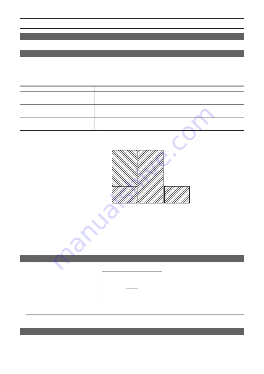
[SPOT]: The image level from the setting value of [ZEBRA1 DETECT] to the setting value of [ZEBRA2 DETECT] is displayed in the zebra pattern.
[ZEBRA2]
Image level
[ON]
[OFF]
[SPOT]
[109%]
[ZEBRA2 DETECT]
[ZEBRA1 DETECT]
[0%]
To display the zebra pattern in the image from the monitor output terminal (<SDI OUT2/IN>, <GL IN/VIDEO OUT>, <HDMI>), set using either of the
following operations.
f
Set the main menu
→
[IN/OUT SEL]
→
[MON OUT ZEBRA] to [ON].
f
In the [SET03:MON OUT SETUP] screen of SmartUI, set [ZBR] to [ON].
Set with following operation to display the zebra pattern in the image of <SDI OUT1> terminal.
Set the main menu
→
[IN/OUT SEL]
→
[SDI OUT1 ZEBRA] to [ON] or [MON ZEBRA].
Displaying the center marker
Displays when setting an item other than [OFF] in the main menu
→
[DISPLAY SETUP]
→
[CENTER MARK].
@
@
NOTE
t
It is not displayed in the image from the <SDI OUT1>, <SDI OUT2/IN>, and <GL IN/VIDEO OUT> terminals.
It can be displayed in the image of the <HDMI> terminal when the main menu
→
[IN/OUT SEL]
→
[HDMI OUT SIGNAL] is set to [VF].
Displaying the safety zone marker
The items you select the main menu
→
[DISPLAY SETUP]
→
[SAFETY MARK] are displayed.
The size of the safety zone marker can be changed in the main menu
→
[DISPLAY SETUP]
→
[SAFETY AREA].
Содержание AJ-PX380G
Страница 9: ...Before using the camera read this chapter Chapter 1 Overview ...
Страница 165: ...Details displayed on the viewfinder are described Chapter 8 Display ...
Страница 192: ...This chapter describes how to use the camera by connecting to network Chapter 10 Network Connection ...
Страница 213: ...Maintenance and error messages of the camera are described Chapter 11 Maintenance ...
Страница 219: ...This chapter describes the specifications of this product Chapter 12 Specification ...


