8 Error handling
−
70
−
8 Error handling
If the motorized actuator or controller does not operate correctly during actuator operation, take the
appropriate actions by referring to the information provided in this chapter. If normal operation cannot be
restored after following the suggested actions, please call our Technical Support Line.
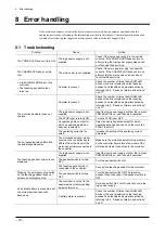
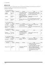
8.1 Troubleshooting
Problem Cause
Action
The POWER LED does not turn ON.
The logic power supply is not
supplied.
Check if the logic power supply is connected
correctly. If the POWER LED does not turn on
after cycling the logic power supply please call
our Technical Support Line.
The CHARGE LED does not turn
ON.
The main power is not supplied.
Check if the main power supply is connected
correctly. If the CHARGE LED does not turn on
after cycling the main power, please call our
Technical Support Line.
•
A red ALARM LED blinks on the
controller.
•
The teaching pendant screen
turns red.
An alarm is present.
Check the number of times the ALARM LED
blinks or the error displayed on the teaching
pendant, and identify an appropriate action by
referring to 8.2, “Causes of alarms and actions”
on p.71.
An alarm is present.
Check the number of times the ALARM LED
blinks or the error displayed on the teaching
pendant, and identify an appropriate action by
referring to 8.2, “Causes of alarms and actions”
on p.71.
The logic power supply is not
supplied.
Input the logic power supply confirm that a green
POWER LED is on, and then start operation.
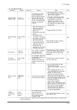
The STOP input is turned ON.
Turn the STOP input OFF.
An operating data number for
which no operating data has
been set is selected.
Select an operating data number for which
operating data has been set, and then turn the
START input ON.
The motorized actuator does not
operate.
The operating current is too
small.
Increase the setting of the operating current
parameter.
The set speed/position differs from
the actual speed/position.
The motorized actuator model
shown on the controller key is
different from the model of the
motorized actuator connected to
the controller.
Make sure the motorized actuator model shown
on the controller key matches the model of the
motorized actuator connected to the controller.
The logic power supply is not
supplied.
Input the logic power supply confirm that a green
POWER LED is on, and then start operation.
The pendant switch is turned
OFF.
Turn the pendant switch ON.
The teaching pendant screen is not
displayed.
The teaching pendant is not
connected to the controller.
Connect the teaching pendant to the controller.
Pressing the emergency stop button
on the teaching pendant does not
actuate an emergency stop.
The pendant switch is turned
OFF.
Turn the pendant switch ON. The teaching
pendant cannot be used if the pendant switch is
OFF.
The controller is not set to the
absolute mode (factory setting:
incremental mode).
Set mode switch No.3 to ON, and then cycle the
logic power supply.
An optional battery is connected, but
the current position cannot be
backed up.
A battery alarm is present.
Check the number of times the ALARM LED
blinks or the error displayed on the teaching
pendant, and identify an appropriate action by
referring to 8.2, “Causes of alarms and actions”
on p.71.
Содержание EZ limo ESMC-A2
Страница 92: ......

