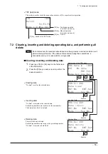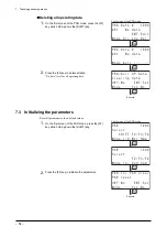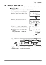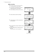
7 Teaching pendant operation
−
57
−
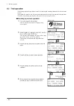
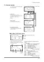
7.5 Monitor
function
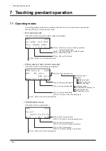
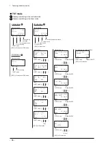
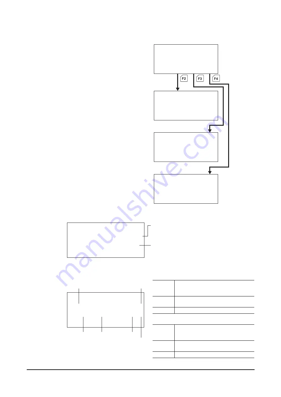
You can monitor I/Os, alarms and operating
data in the EXT mode.
•
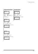
I/O monitor
The status of each I/O is shown.
You can display the statuses of other I/Os by
pressing the [
↑
] and [
↓
] keys.
ON: “
∗
”
OFF: “
•
”
•
Alarm monitor
The current alarm status is shown.
•
Operating data monitor
The positioning operating data currently
executed is shown.
' : 6 + 1 + P
5 6 # 4 6 # % .
( 4 ' ' 5 6 1 2
/ Q F G
' : 6 + &
5 G N # E V
2 Q U O O
/ Q F G + 1 # N O & C V C
' : 6 # N O 0 Q Y
' T T Q T
0 Q ' T T Q T
/ Q F G % N T * K U V
' : 6 & C V C
# D U + P E + P E
2 Q U O O
/ Q F G
•
I/O monitor
•
Alarm monitor
•
Operating data monitor
First screen of the EXT mode (Example of controller mode)
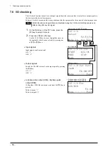
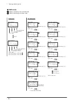
Description of I/O monitor screen
' : 6 + 1 + P
/ $ K V
/ / /
/ Q F G
Bit image corresponding to data number
1: ON
0: OFF
∗
: ON
•
: OFF
The signals are aligned in the following orders from
the left.
•
Controller mode
Input
signals
START, ACL (CK)
∗
, FREE, STOP, M5, M4,
M3, M2, M1, M0, HOME/PRESET,
REQ, /EMG, FWD, RVS
Output
signals
/ALM, MOVE, T-UP (OUT1)
∗
,
AREA (OUT0)
∗
, END (OUTR)
∗
Sensor
+LS, –LS, HOMELS
∗
When the ABS data is loaded
•
Driver mode
Input
signals
ACL (CK)
∗
, FREE, C.OFF,
HOME/PRESET, REQ, /EMG, FP, RP,
HMSTOP
Output
signals
/ALM, MOVE, T-UP (OUT1)
∗
,
TIM (OUT0)
∗
, END (OUTR)
∗
Sensor
+LS, –LS, HOMELS
On the screen for monitoring all I/Os, the
symbols (
∗
and
•
) correspond to the respective
I/Os (from the far left).
' : 6 + 1 # N N
+ 0
1 7 6
5 + 0
/ Q F G
END
(OUTR)
∗
/ALM
START
+LS
HOMELS
RVS
∗
When the ABS data is loaded
Содержание EZ limo ESMC-A2
Страница 92: ......


