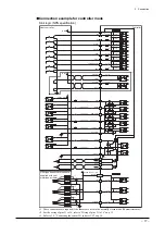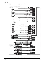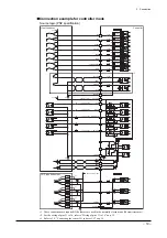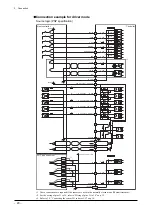
1 Introduction
−
6
−
1.5 Names and functions of front panel
Logic power
supply terminals
Logic power
supply terminals
POWER LED
ALARM LED
•
ESMC-A2
,
ESMC-C2
•
ESMC-K2
CHARGE LED
Mode switch
Battery
connector
Mode switch
Battery
connector
Sensor
connector
Sensor
connector
I/O connector
I/O connector
Emergency stop
output terminal
Emergency stop
output terminal
Motor connector
Motor connector
Main power
supply terminals
Main power
supply terminals
Protective Earth
Terminal
Pendant connector
Controller key
Controller key
Pendant switch
Pendant connector
Pendant switch
POWER LED
ALARM LED
∗
The controllers shown above are equipped with a controller key.
Name Function
Controller key
The controller key stores parameters relating to motorized actuator control. If you have
purchased a controller only, no controller key is supplied. For details, refer to 1.6,
“Controller key” on p.7.
Pendant switch
ON: The teaching pendant can be used.
OFF: The teaching pendant power is turned off. (The emergency stop button on the
teaching pendant is also disabled.)
Pendant connector
This connector is used to connect the pendant connector or PC interface cable.
Logic power supply terminals
This connector is used to connect the logic power supply.
Emergency stop output terminal
This connector is used to connect the Emergency stop circuit.
Motor connector
This connector is used to connect the motor cable of the motorized actuator.
CHARGE LED
∗
This LED will be lit when the main power supply and logic power supply are input to the
controller. It will also be lit when hazardous voltage is still present in the controller.
It takes approx. 4 minutes after the power is turned off until the CHARGE LED turns off.
Main power supply terminals
This connector is used to connect the main power supply.
POWER LED
The green LED is lit while voltage is being supplied to the logic power supply terminals.
ALARM LED
The red LED blinks when an alarm is generated (upon activation of the protective
function or emergency stop).
Mode switch
Use this switch to set various controller functions. If you have changed any setting, be
sure to cycle the logic power supply. The new setting will not become effective until the
logic power supply is cycled.
Not used
ABS/INC ON:
Absolute
OFF:
Incremental
1P/2P selection ON: 1-pulse input mode
OFF: 2-pulse input mode
Mode ON: Driver mode
OFF: Controller mode
Battery connector
If your controller is used in the absolute mode, connect an optional battery (sold
separately) to this connector.
Sensor connector
This connector is used to connect the sensor input.
I/O connector
This connector is used to connect the user I/O.
Protective Earth Terminal
∗
The controller’s Protective Earth Terminal
∗
Not available on the
ESMC-K2
.
Содержание EZ limo ESMC-A2
Страница 92: ......


