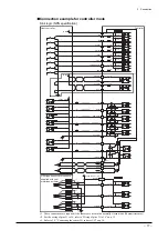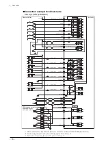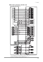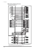
3 Connection
−
16
−
•
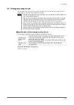
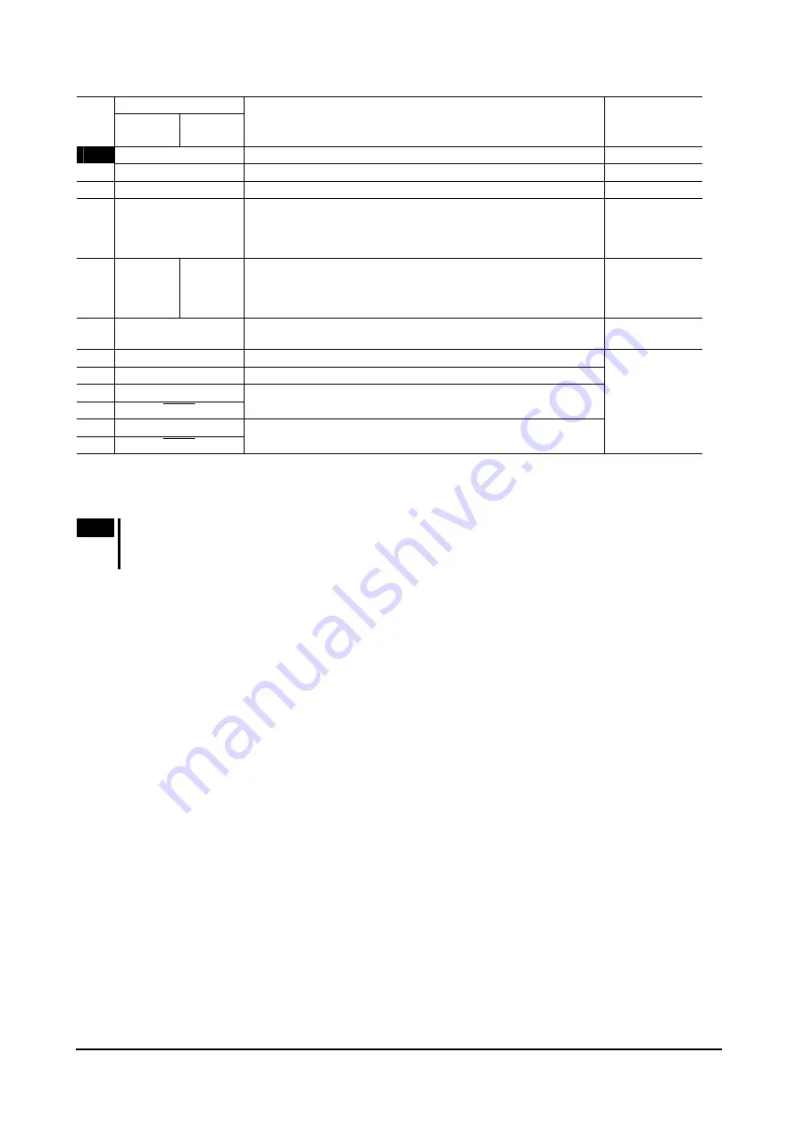
Output signals
Signal name
Pin
No.
Controller
mode
Driver
mode
Description Reference
1
OUT-COM
∗
1
Power supply input for output signals
−
2
ALM
Output when an alarm has occurred (Normally close).
−
3
MOVE
Output while the motorized actuator is operating.
−
4 END/OUTR
∗
2
END: Output when the difference between the command position
and actual position is within the END signal detection width at the
end of operation.
OUTR: Used to read the current position.
OUTR: p.36
5
AREA/
OUT0
∗
2
TIM/
OUT0
∗
2
AREA: Output when the moving part has entered the specified area
or stopped inside the area.
OUT0: Used to read the current position.
TIM: Output when the excitation sequence is at step 0.
AREA: p.34
OUT0: p.36
TIM: p.34
6 T-UP/OUT1
∗
2
T-UP: Output when a push-motion operation has been completed.
OUT1: Used to read the current position.
T-UP: p.30
OUT1: p.36
20
ASG1
A-phase pulse output (Open collector)
21
BSG1
B-phase pulse output (Open collector)
22 ASG2
23 ASG2
A-phase pulse output (Line driver)
24 BSG2
25 BSG2
B-phase pulse output (Line driver)
p.33
∗1
Connect this signal to ground if your controller is used in the NPN mode, or connect it to 24 VDC if the controller is used in the PNP
mode.
∗2
If the REQ input is ON, these signals switch to the OUTR, OUT0 and OUR1 outputs, respectively. If the REQ input is OFF, they switch
to the END, AREA and T-UP outputs, respectively.
Note
Do not directly connect a host controller adopting TTL circuits. If such controller is connected directly, the output
voltage will not drop to 0 V even after an output signal turns ON. As a result, the host controller may not be able
to detect the ON status of the output.
Содержание EZ limo ESMC-A2
Страница 92: ......


