3 Connection
−
14
−
3.5 Connecting the sensor I/O and user I/O
Assembly method
1.
Solder the lead wires to the supplied I/O connectors (the figure shows pin assignments as
viewed from the soldered side).
Applicable lead wire: AWG28 to 26 (0.08 to 0.14 mm
2
)
36
35
2
1
"1" is engraved
20
19
20
19
12
11
2
1
"1" is engraved
•
User I/O
•
Sensor I/O
2.
Assembling the connector.
M2
Tightening torque:
0.3 to 0.35 N·m
(42.6 to 49.7 oz-in)
M2.5
Tightening torque:
0.5 to 0.55 N·m
(71.0 to 78.1 oz-in)
Pin assignments of sensor I/O connector
Pin No.
Signal name
Description
1, 11, 19
IN-COM2
Power supply input for sensor
13
+LS
+LS limit sensor input
14
–LS
–LS limit sensor input
15
HOMELS
HOME sensor input
Note
•
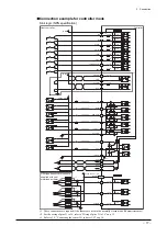
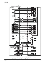
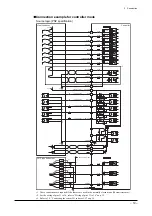
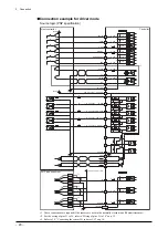
If a photomicrosensor is used and the sensor wiring length is longer than 2 m, provide
an electrolytic capacitor (10 µF, 50 V) at a position within 2 m of the sensor. Refer to the
connection examples shown on pp.17 to 20.
•
When sensors are used, always set the I/O parameter “LS detection enable/disable” to
“Enable.” If it is set to “Disable,” a stop action will not be activated even when a sensor
is detected.
•
IN-COM2 is insulated from IN-COM1 in the user I/O connector. When using sensors, be
sure to connect the power supply.
Содержание EZ limo ESMC-A2
Страница 92: ......


