6 First time operation
−
47
−
6.
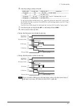
Check the lighting condition of the LED.
POWER LED
ALARM LED
CHARGE LED
Description
On (green)
Off
On (red)
Normal status
Off
Off
On (red) or Off
On (green)
On (red)
On (red) or Off
On (green)
Blinking (red)
On (red) or Off
See 8.1 “Troubleshooting” on p.70.
If you have selected the absolute mode in step 3, an absolute position loss alarm (Err33) generates and
the ALARM LED blinks seven times. Press the
[F4]
key on the teaching pendant or turn the ACL input
ON to reset the alarm.
Once the battery is fully charged, the absolute position loss alarm (Err33) should no longer generate.
7.
Set data using the teaching pendant
EZT1
or data editing software
EZED2
.
8.
Perform return-to-home operation.
•
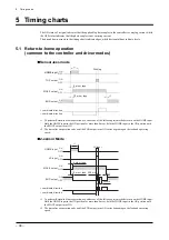
Timing chart at power on (controller mode only)
START input
ALM output
Main power input
Logic power
supply input
OFF
ON
OFF
ON
OFF
ON
OFF
ON
2 s or more
2 s or less
2 s or less
0 s or more
Motor excitation
Motor is excited
•
Timing chart at power on (driver mode only)
Pulse input
2 s or more
2 s or less
0 s or more
2 s or less
ALM output
Main power input
Logic power
supply input
Motor excitation
Motor is excited
OFF
ON
OFF
ON
OFF
ON
OFF
ON
Note
Do not turn ON the FWD input or RVS input before turning on the logic power supply. It
will cause a main power OFF detection alarm (Err23) to generate.
Содержание EZ limo ESMC-A2
Страница 92: ......

