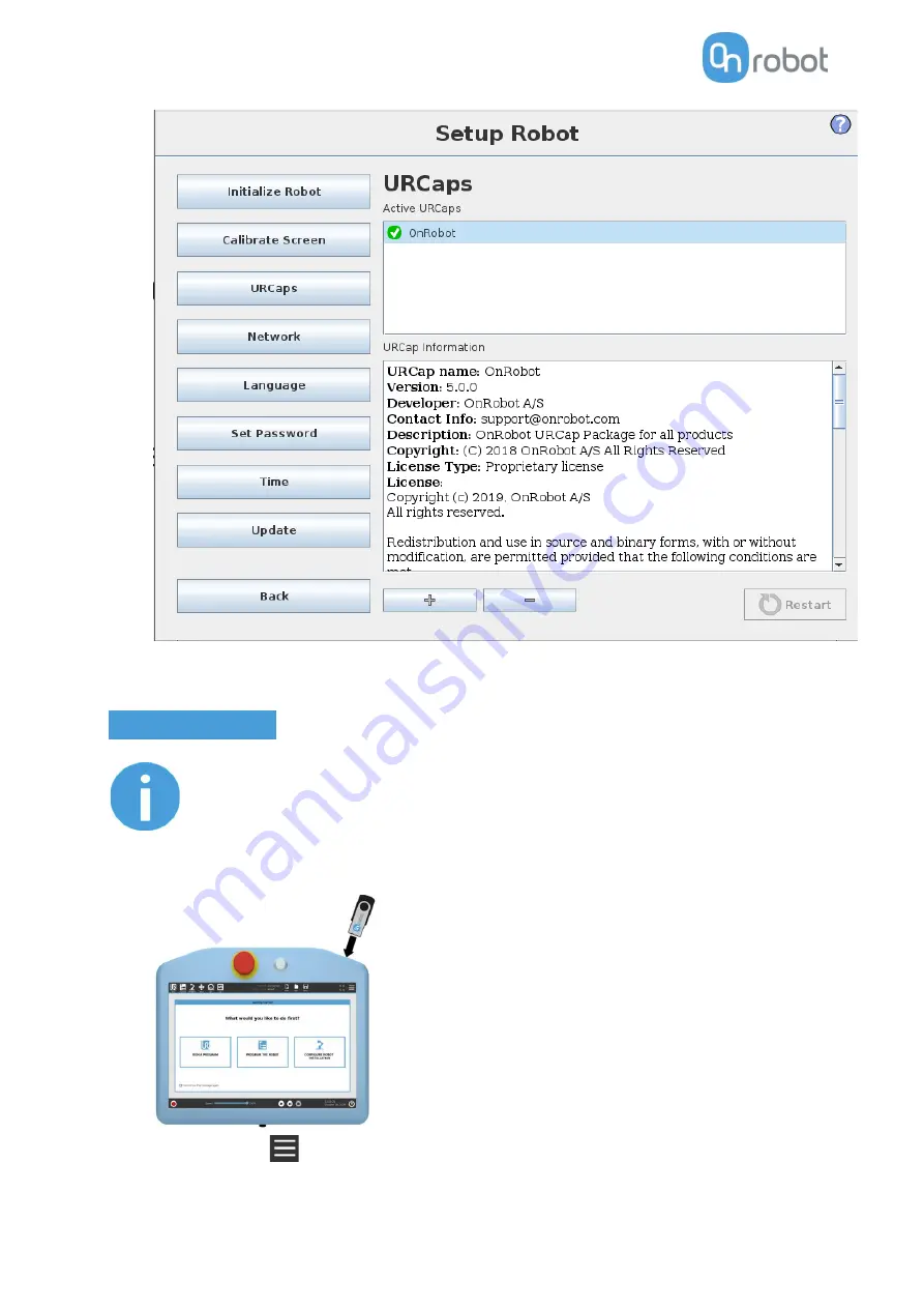
OnRobot VGC10 Скачать руководство пользователя страница 26

Installation 

26 


5.


Initialize the robot. 


UR e-Series 


NOTE: 

The minimum UR  PolyScope version is 

5.4

.  Please remove all  previous 

OnRobot URCap version(s) before the installation. 


1.


Insert the OnRobot USB drive in the USB slot on the top right side of the Teach Pendant.  


2.


Then tap on the 

  menu (top right corner of the screen), then from the 

System

 section tap on 

the 

URCaps


menu. 

Содержание VGC10

Страница 1: ...USER MANUAL FOR UR ROBOTS ORIGINAL INSTRUCTION EN v1 05...

Страница 2: ...1 Overview 12 4 2 Mounting 12 4 2 1 Quick Changer options 13 4 2 2 Tools 15 4 3 Wiring 21 4 3 1 Tool data cable 22 4 3 2 Ethernet cable 23 4 3 3 Power supply 24 4 4 Software setup 25 4 4 1 Install UR...

Страница 3: ...7 2 Mechanical Drawings 179 7 2 1 Adapter plate s 179 7 2 2 Mountings 179 7 2 3 Tools 184 7 3 Center of Gravity 194 8 Maintenance 196 9 Warranties 199 9 1 Patents 199 9 2 Product Warranty 199 9 3 Disc...

Страница 4: ...koGripper v2 RG2 v2 RG2 FT v2 RG6 v2 VG10 v2 VGC10 v1 Sensors Version HEX E QC v3 HEX H QC v3 Where applicable the combination of the products is also coveredin the manual NOTE Generally the products...

Страница 5: ...his is an instruction relevantforthe RG2 product only RG2 FT This is an instruction relevantforthe RG2 FT productonly VG10 This is an instruction relevantforthe VG10 product All textwithoutthese visua...

Страница 6: ...tionof the integrator Collecting all documentationin a technical file including the risk assessmentandthismanual 2 1 IntendedUse OnRobottools are intendedto be usedon collaborative robotsand light ind...

Страница 7: ...set forth in the standards and regulationsof the countrywhere the robotis installed Anysafetyinformationprovidedinthismanual mustnotbe construedas a warranty by OnRobot A S that the robot application...

Страница 8: ...e movement OnRobot A S have identified the potential hazards listed below as significant hazards that must be consideredbythe integrator Objectsflyingfrom OnRobottools due to loss of grip Objectsfalli...

Страница 9: ...cture below the safetycontrolsystemstopsmotion of the twoarms of the product Motionis then preventedaslong as one or both of the two buttonsare activated If this happenswhile runningthe robot program...

Страница 10: ...l be dropped due to the loss of gripper power If Dual Quick Changer is usedit will cycle the powerforbothsides NOTE If the robot program is started and one of the safety switches has been previouslypr...

Страница 11: ...equiresdifferentstepsorscreensitis highlightedand referredas CB3 series e Series There are twowayshow the product s couldbe usedon bothUR series Modesof Operation via Compute Box workswithall products...

Страница 12: ...stepswill be required Mountthe components Wire the cables Setupthe software In the followingsections these installation stepswill be described 4 2 Mounting Requiredsteps Mountthe Quick Changeroption M...

Страница 13: ...Quick Changer ISO9409 1 50 4 M6 3 Dowelpin 6x10 ISO2338 h8 4 Adapter Robot tool flange ISO 9409 1 50 4 M6 Use 10 Nmtightening torque Dual Quick Changer Dual Quick Changer 1 M6x20mm ISO14580 8 8 2 Dua...

Страница 14: ...C HEX E H QC 1 HEX E H QC sensor 2 M4x6mm ISO14581 A4 70 3 M6x8mm NCN20146 A4 70 4 HEX E H QC adapter 5 Adapter Robot tool flange ISO 9409 1 50 4 M6 Use 1 5 Nm tightening torque for M4x6mm Use 10 Nmti...

Страница 15: ...tongue will keepthe lower part locked once mounted Step2 Flip the tool until it is fully mated and youhear a clicking sound To unmount the tool press the aluminum button on the Quick Changer and repe...

Страница 16: ...you heara clicking sound To unmountthe tool pressthe aluminumbutton on the Quick Changerand repeatthe stepsin the reverse order To change the relative angle of the gripper to the Quick Changer first...

Страница 17: ...nd you heara clicking sound To unmountthe tool pressthe aluminumbutton on the Quick Changerand repeatthe stepsin the reverse order To change the relative angle of the gripper to the Quick Changer firs...

Страница 18: ...uhear a clicking sound To unmount the tool press the aluminum button on the Quick Changer and repeat the stepsin the reverse order To change the relative angle of the gripper to the Quick Changer firs...

Страница 19: ...nd To unmount the tool press the aluminum buttonon the Quick Changerand repeatthe stepsin the reverse order VGC10 Step1 Move the tool close to the Quick Changeras illustrated The hook mechanism rod an...

Страница 20: ...anger as illustrated The hook mechanism rod and hook tongue will keep the lower part locked once mounted Step2 Flip the tool until it is fully mated and you heara clicking sound To unmountthe tool pre...

Страница 21: ...NOTE VG10 VGC10 can only be attached when the UR controller is started not in IDLE mode and no program is running or completelypoweredoff CAUTION Dual Quick Changercannot be connectedto the Tool Conn...

Страница 22: ...e to the tool For Single or Dual RG2 RG6 VG10 VGC10 or GeckoGripper Use the M8 8pin connector on the Quick Changer or on the Dual Quick Changer Use the cable holderas illustrated on the left CAUTION M...

Страница 23: ...Finally connectthe otherend of the Tool data cable to the Compute Box sDEVICESconnector CAUTION Use only original OnRobot tool data cables Do not cut or extendthese cables CAUTION Quick Changer and Du...

Страница 24: ...anic connectionbetweenthe two 4 3 3 Power supply Connect the supplied power supply to the Compute Box 24V connector NOTE To disconnect the power connector make sure to pull the connectorhousing wheret...

Страница 25: ...be CB3 1 1 Insertthe OnRobotUSBdrive in the USB slot on the right side of the Teach Pendant 2 Selectthe Setup Robot option fromthe main menu thenthe URCaps option 3 Tap on the sign to browse for the O...

Страница 26: ...version is 5 4 Please remove all previous OnRobotURCapversion s before the installation 1 Insertthe OnRobotUSBdrive in the USB slot on the top right side of the Teach Pendant 2 Then tap on the menu t...

Страница 27: ...enwait forthe systemtobe restarted 5 Initialize the robot NOTE For more information on the URCap installation please refer to UR documentation 4 4 2 Uninstall software UR CB3 1 Selectthe Setup Robot o...

Страница 28: ...Installation 28 5 Initialize the robot...

Страница 29: ...e screen then from the System section tap on the URCaps menu 2 Selectthe OnRobotURCapfile 3 Tap on the sign 4 Then the system needs to be restarted for the changes to take effect Tap on the Restart bu...

Страница 30: ...Installation 30 4 4 3 URCap setup For the e SeriesURrobots tapon the Installation tab in the topmenu Thentap on the URCaps...

Страница 31: ...Installation 31 For the CB3 UR robots select the Installation tab then select OnRobot Setup The following screen is shown...

Страница 32: ...on to findnewavailable devices NOTE Touse the newlydiscovereddevicesyoumightneedtorestartPolyScope To do that simply press the Restart now button Remember to save it before if there are any unsaved ch...

Страница 33: ...o check if the change was successful To communicate through the tool connector on an e Series UR robot please set the following configuration 1 Pressthe General dropdownmenuonthe leftside 2 Pressthe T...

Страница 34: ...rvice program is running every 2 seconds In addition to that the Tool IO is setto be logic high and low randomly CAUTION After any error message is shown that is related to the connection to our devic...

Страница 35: ...This displays informationabout the errorsif there is any Device name The Serial number Systemhealth and Firmware versionare shown Update this will update the firmware if an update is available Dependi...

Страница 36: ...screenwill show Overwrite values Automatic overwrite of the robot TCP configuration whenchecked the UR sTCP configuration is automatically overwritten DynamicTCP mode Whenunchecked the TCPisleftuncha...

Страница 37: ...iding could be startedby pressingthe enable buttonandstoppedbypressingthe enable buttonagain Timeout Afterthe set timeoutvalue the hand guiding will be stoppedautomatically The default value is 0 that...

Страница 38: ...on is automatically overwritten DynamicTCP mode Whenunchecked the TCPisleftunchanged Static TCP mode For furtherinformationand bestpracticeson the TCP settingsee TCP Configuration section TCP offset S...

Страница 39: ...ttonagain Timeout Afterthe set timeoutvalue the hand guiding will be stoppedautomatically The default value is 0 thatsetsthe timeoutto infinite Mounting In the normal view of the panel the selectedmou...

Страница 40: ...normal view of the panel the set values are shown To change the values press on and the following screenwill show Calibrated value shows the value to use for the application This value is calculated...

Страница 41: ...gripper will close and make a measurement to set the right offset Wait until the gripper is closed 5 Once the gripper is openedthe measurementisready 6 Tap on Yesto save the newoffsetandthe setupis f...

Страница 42: ...on is automatically overwritten DynamicTCP mode Whenunchecked the TCPisleftunchanged Static TCP mode For furtherinformationand bestpracticeson the TCP settingsee TCP Configuration section TCP offset S...

Страница 43: ...re shownin the image below TCP In the normal view of the panel the TCP of the robot can be overwrittenbythe TCP of the tool by pressingthe Automatic overwrite of the robot TCP configuration checkbox T...

Страница 44: ...he Linear offset X Y Z andthe Rotation in RPY Roll Pitch Yaw valuestoadjustthe OnRobot device dependentcalculatedTCP Mounting In the normal view of the panel the selectedmountingangle is shown To sett...

Страница 45: ...e Quick Changer is orientated with the part 1 on the left side and the part 2 on the right side The numbers are written on the side of the Quick Changerthat connectsto the robot 2 Select the angle of...

Страница 46: ...cify the distance from the inside of the gripper s aluminum fingertip to the reference pointonthe attachedfingertip The Fingertipoffsetforthe StandardFingertipsis4 6 mm whenplacedin the innerside and...

Страница 47: ...screenwill show Overwrite values Automatic overwrite of the robot TCP configuration whenchecked the UR sTCP configuration is automatically overwritten DynamicTCP mode Whenunchecked the TCPisleftunchan...

Страница 48: ...f the panel the selected attachmenttypessuchas Standard Pipe Cup Adaptor Cups Adaptor Pipe Cup and For customizationare mentioned Thisconfigurationpanelis usedto set the TCP in the right position as w...

Страница 49: ...CP at the centerof the endside of the cups considering also the adaptor height see table below Adaptor Pipe Cup Device with the adaptor with the extension pipe in the middle with a cup This selectionw...

Страница 50: ...Installation 50 The table belowprovidesan overviewof the different attachmentcombinations the TCPvaluesthat will be set in the robot and an image with a visual representationof the TCPlocation...

Страница 51: ...hment TCP x y z mm Image Standard 0 0 100 Pipe Cup 17 17 150 Adaptor Cups 0 0 110 Adaptor Pipe Cup 0 0 160 For customization 0 0 75 The TCP valueshave their origin in the top part of the gripperas sho...

Страница 52: ...reenwill show Overwrite values Automatic overwrite of the robot TCP configuration whenchecked the UR sTCP configuration is automatically overwritten DynamicTCP mode Whenunchecked the TCPisleftunchange...

Страница 53: ...o the installation stepsin the previoussection The OnRobotdevicescan be operatedin 3 differentways URCap Commands provide aneasy wayto program an application UR Toolbar makesit simple to operate the t...

Страница 54: ...the robot to grip a part by applying the specifiedpreloadforce and movingat the specifiedspeed To grip a part with the Gecko Gripper first the pads are pulled out and then the robot is moved down wit...

Страница 55: ...cannot exertforcesabove 50N Robot Speed Specifythe robot s downwardspeedduringthe pick motion Valuesbetween0 and 300 mm s Pad Control pressto move the Geckopadsin pressto move the Geckopadsout Payload...

Страница 56: ...56 GeckoGripper Release The Gecko Gripper Release commandcontrols the GeckoGripper and the robot to release the part at a specificwaypoint Pad Control pressto move the Geckopadsin pressto move the Gec...

Страница 57: ...obot device dependentcalculatedTCP Payload ModifyTool payload If enabledthe UR spayload will be overwritten Mass enter the workpiece mass that is attached to the device The device own mass is added au...

Страница 58: ...F T Zero command at the beginningof the F T Control command andmake sure the tool is not in contact with any object before starting the F T Control otherwise the commandmaynot workproperly Compliant...

Страница 59: ...advanced optionsIf checkedthenmore optionsbecome available I gainF The force controllercanbe tunedwiththisintegralgain parameter If anyovershootsorvibrations occur try loweringthe gain value I gain T...

Страница 60: ...r values Increasing this parameter has the following effects less overreaction stability increase If the force control is too slow that is the tool occasionally leaves the surface instead of continual...

Страница 61: ...canbe addedin the same way To remove awaypoint use the Structure tab Delete button Alternatively F T Waypoint or F T Path could be addedas a child node of the F T Move command by usingthe Structure ta...

Страница 62: ...ncan be set If the Use absolute values optionisenabled thenitisnotimportantwhetherthe enteredvalueispositive or negative e g Fz 3 otherwise the sign defineshow the thresholdis calculated e g Fz 3 or F...

Страница 63: ...electit to record a newpath If there is a recordedPaththat is not saved there is an Unsaveditemin the List NOTE Only one unsavedPath can exist and it will be overwrittenby starting a Path recordingwhi...

Страница 64: ...nificant deviationfromthe recordedtrajectory NOTE Rotational movements related to translational movements in Path recordingare limitedto2 8 degrees mmorless since alargerratiowould cause the Robot to...

Страница 65: ...erwise the commandmay not stopat the given force torque limit To operate the F T Search commandtap on the Add Waypoint button to add an F T Waypointas a child node More waypointscanbe addedin the same...

Страница 66: ...tom Base Custom Tool according to the UR s reference frames The Customcoordinate systemsare calculatedfrom the basiscoordinate systemandthe givenRoll Pitchand Yaw values For the Custom Base coordinate...

Страница 67: ...commandsto achieve rotationswithouttranslational movements Type The type of the waypoint Itcan be setto Fixed Relative orVariable Target TCP pose The position representedbythe waypointin the robotrout...

Страница 68: ...e waypoint in the robot route A variable can define the target pose The variable needsto be createdfirst Relative X Y Z RX RY RZ the distances and rotations this waypoint represents compared to the pr...

Страница 69: ...robot will stop once one of the setlimits is reached The force limiting can be mixedwith an externalI Osignal e g stop if Fz 5 AND digital_in 7 True NOTE To cancel any force torque offset execute an F...

Страница 70: ...D T3D available optionsmore than one can be set In this case if any of those values reached the set threshold the stop is triggered The valuesequal tozero are neglected If the Absolute optionisenabled...

Страница 71: ...f is enabled then the set digital I O will also be monitored and once the condition is met along with the force torque limit the robot will be stopped e g stopif Fz 5 AND digital_in 7 True This comman...

Страница 72: ...any object before starting the F T Insert Part otherwise the command may not stop at the given force torque limit Pushingforce The force targetusedfor the force control to gentlypush the part into th...

Страница 73: ...and the insertion is progressingat a slowerpace it is interruptedandconsideredunsuccessful If itis set to zero this exitcriterium is neglected Compliance orLimit Fx Fy Tx Ty Tz The axisselectionthatne...

Страница 74: ...obot device dependentcalculatedTCP Payload ModifyTool payload If enabledthe UR spayload will be overwritten Mass enter the workpiece mass that is attached to the device The device own mass is added au...

Страница 75: ...W Width and F Force and if selected Depth compensation ON and or Automatic centering ON The different functionsare explainedbelow NOTE To cancel any force torque offset execute an F T Zero command at...

Страница 76: ...essed the followinggraphical illustration will appearin a new page Current width The numbershowsthe Current widthvalue will setthe Currentwidthastargetwidth If usedwhenagraspisdetected see imagebelow...

Страница 77: ...TCP checkbox is checkedthe TCP will be set at the furtherend of the part It requiresthe followingtwo parameterstobe given Part length L the distance betweenthe centerpointof the fingertipsensorsandth...

Страница 78: ...stop Highermassand bigger distance can be vibrating more easily Timeout The maximal allowedtime forthe whole insertionfunction If it is setto zero this exitcriterium is neglected Expectedspeed The mi...

Страница 79: ...the return value of the command See returnvaluesin the ReturnValues section F T Control Applications suchas polishing deburring sanding or grinding may require holding constantforce torque to a define...

Страница 80: ...mcoordinate systemsare calculatedfrom the basiscoordinate systemandthe givenRoll Pitchand Yaw values For the Custom Base coordinate system it is also possible to use the Get TCP orientation buttonto s...

Страница 81: ...comparedtothe valuessetbythe F T Control command andappliescorrection basedon this error P gain F and P gain T The proportional term produces a correction that is proportional to the current errorval...

Страница 82: ...bove 1 If the force control is reacting to changes too slowly that is it keeps pushing the surface hard after touching it try decreasingthe I Gain As a rule of thumb it is recommendedtouse values P Ga...

Страница 83: ...canbe addedin the same way To remove awaypoint use the Structure tab Delete button Alternatively F T Waypoint or F T Path could be addedas a child node of the F T Move command by usingthe Structure ta...

Страница 84: ...ncan be set If the Use absolute values optionisenabled thenitisnotimportantwhetherthe enteredvalueispositive or negative e g Fz 3 otherwise the sign defineshow the thresholdis calculated e g Fz 3 or F...

Страница 85: ...electit to record a newpath If there is a recordedPaththat is not saved there is an Unsaveditemin the List NOTE Only one unsavedPath can exist and it will be overwrittenby starting a Path recordingwhi...

Страница 86: ...nificant deviationfromthe recordedtrajectory NOTE Rotational movements related to translational movements in Path recordingare limitedto2 8 degrees mmorless since alargerratiowould cause the Robot to...

Страница 87: ...erwise the commandmay not stopat the given force torque limit To operate the F T Search commandtap on the Add Waypoint button to add an F T Waypointas a child node More waypointscanbe addedin the same...

Страница 88: ...tom Base Custom Tool according to the UR s reference frames The Customcoordinate systemsare calculatedfrom the basiscoordinate systemandthe givenRoll Pitchand Yaw values For the Custom Base coordinate...

Страница 89: ...commandsto achieve rotationswithouttranslational movements Type The type of the waypoint Itcan be setto Fixed Relative orVariable Target TCP pose The position representedbythe waypointin the robotrout...

Страница 90: ...e waypoint in the robot route A variable can define the target pose The variable needsto be createdfirst Relative X Y Z RX RY RZ the distances and rotations this waypoint represents compared to the pr...

Страница 91: ...Operation 91 F T Zero The F T Zero commandcan be usedtozero the force torque values This commandhas no returnvalue...

Страница 92: ...obot device dependentcalculatedTCP Payload ModifyTool payload If enabledthe UR spayload will be overwritten Mass enter the workpiece mass that is attached to the device The device own mass is added au...

Страница 93: ...ctwhich one of the twogrippersperformsthe action Target Width The target gripping width can be set by using the Save as Target Save Graspbutton recommended orbytypingit in manually Whenpressed the gri...

Страница 94: ...e will setthe Currentwidthastargetwidth If usedwhenagraspisdetected see image below this will setthe target widthas current width 3 mm if the workpiece is grabbedexternallyand 3 mm if the workpiece is...

Страница 95: ...obot device dependentcalculatedTCP Payload ModifyTool payload If enabledthe UR spayload will be overwritten Mass enter the workpiece mass that is attached to the device The device own mass is added au...

Страница 96: ...um The higher the vacuumis set upto 80 kPa the more the lifting poweris Payload mass the workpiece weight can be entered The URCap software will then perform the calculation of the resultingpayload ma...

Страница 97: ...taHEX E HQCbutusedonanE seriescontrollerthe following extraoption becomesavailable Seek whenchecked the same seekingaction will happenas above Since the auto leveling part is not usedthe VG grippers n...

Страница 98: ...rogram the commandname will show 1 or 2 to indicate which grippersis performingthe action Channel s Selectwhich channel performthe action It is possible to select channelA B or both To see which one i...

Страница 99: ...obot device dependentcalculatedTCP Payload ModifyTool payload If enabledthe UR spayload will be overwritten Mass enter the workpiece mass that is attached to the device The device own mass is added au...

Страница 100: ...e toolbar in the e Series press on the UR icon on the top right side Then press on the OnRoboticon Each OnRobotEnd of ArmTooling hasits ownfunctionalityand that is explainedinthe sectionsbelow To open...

Страница 101: ...Operation 101 To enable disable the toolbar press on the OnRobot logo on the top right corner and check uncheckthe Enable toolbarcheckbox...

Страница 102: ...Operation 102 The table belowshowsthe page where the toolbar foreach OnRobotdevice is explained Gecko 103 HEX E H QC 104 RG2 FT 106 RG2 RG6 109 VG10 VGC10 110...

Страница 103: ...sin the How to access the toolbar section The toolbar for the Geckois shownbelow pressto get the Geckopadsin pressto getthe Geckopadsout This buttononly appearsif the padsare wornand needstobe replace...

Страница 104: ...possible to lock some of the axesto reduce the degreesof freedom The toolbar contains the available axes the enable button the zero button and the snap to axesbutton To selectan axis tap on the approp...

Страница 105: ...button while touching the tool To stop handguiding the UR Robot pressthe enable button NOTE The handguiding could be configured inthe OnRobotinstallation page to be enabledwitha single tap on the enab...

Страница 106: ...selectwhich one performsthe action Current width showsthe value Force Setthe target gripping force These are openandclose hold to runbuttons This button can be usedto reactivate the RG2 or RG6 after...

Страница 107: ...he Xandthe Y itemsare selectedtolimit the movementalongthe Xand Y axis planar NOTE The used coordinate systemis the Tool To deactivate any axisthat has beenselected taponthe item again NOTE It is poss...

Страница 108: ...ed inthe OnRobotinstallation page to be enabledwitha single tap on the enable button instead of holding and stopped with a second tap However the holding behavioris recommendedforincreasedsafety NOTE...

Страница 109: ...rrent width showsthe value Force Setthe target gripping force These are openandclose hold to runbuttons This button can be usedto reactivate the RG2 or RG6 after any of the gripper s SafetySwitch is a...

Страница 110: ...rmsthe action Mode SelectIndependent actuate achannel individually or Tandem actuate both channelstogether Actual vacuum showsthe current vacuumin each channel Target vacuum definestargetvacuumin each...

Страница 111: ...ript function rg_grip rg_width force tool_index 0 blocking True depth_compensation False popupmsg True Blocking True the functionwaits for the gripperto finish the grip command popupmsg future functio...

Страница 112: ...canbe used E g 0 6 600 ms If not set this parameterdefaultsto5 seconds alert Whetherthe grip shouldbe monitoredaftervacuum grip is established If vacuum is lost while handling a workpiece a popup warn...

Страница 113: ...econdary vg10_idle channel tool_index Commands the VG10 to idle the selected channel When a channel is in idle the power consumption is slightly lower but parts may stick to the suction cup as the air...

Страница 114: ...Static TCP mode Recommendedtobe used Dynamic TCP mode The mode couldbe selectedonthe TCPpanelinthe OnRobotInstallation see inthe URCap setupsection In the followingthese twomodeswill be described Stat...

Страница 115: ...sinthe UR sMove commandinawaythat the referencingTCP is setfirst So if only a single OnRobot device is used before the Waypoints are defined set the UR s Move command sTCP to use the OnRobot_Single If...

Страница 116: ...stedimmediately However the Active TCPisoverwrittendirectly thereis alsoanOnRobot definedTCP thatis called OnRobot_Default This is the name in both the Single and Dual device case It is recommended to...

Страница 117: ...hing As summaryhere is a code example Single Dual Recommendedtoset OnRobot_DefaultTCPasthe UR s DefaultTCP Recommendedtoset OnRobot_DefaultTCPasthe UR s DefaultTCP Before eachprogramexecutionmake sure...

Страница 118: ...or torque greaterthan the setlimit was detected 1 The search endedwithoutdetectingaforce or torque greaterthan the setlimit 3 The search wasinterruptedbya command 11 The search cannot start because t...

Страница 119: ...The return value for the OnRobotcommands HEX E H QC FeedbackVariable Unit Description on_return The return value for the OnRobotcommands F3D N Lengthof the 3D force vector F3D sqrt Fx2 Fy2 Fz2 FT_Base...

Страница 120: ...xNm list of Fx Fy Fz Tx Ty Tz forthe right fingersensor FT_Tool 3xN 3xNm Force and torque valuescalculated in the Tool Coordinate system inan array Part_Width mm The actual value of the detectedpartwi...

Страница 121: ...er at 0 mmwidth rg_DepthRel mm Distance the robot due to depthcompensation has movedtowardsthe z axeshavingas reference the previousgripper swidth rg_Grip_detected True False True if Gripperhasdetecte...

Страница 122: ...outputthatcouldbe used These inputsandoutputscanbe programmed through the OnRobot WebLogic that requires the Ethernet interface to be used only for programmingtime 6 1 2 Web Client To accessthe WebCli...

Страница 123: ...entered passwordmustbe atleast 8 characterslong Once signedin the followingtop menusappear Devices Monitorand control the connecteddevices e g grippers Configuration Change the Compute Box ssettings W...

Страница 124: ...ings e g change password addnew user Selectthe language of the WebClient In the following these menuswill be described Devicesmenu To control monitora device click onthe Selectbutton Gecko 125 HEX E H...

Страница 125: ...om the bottomof the gripper The state of the gripper could be Pad position Padsare eitherIn or Out out meansreadyforgripping Part detected the set preloadforce limit is reached and objectdistance is 1...

Страница 126: ...are restoredtothe defaultvalue 90N on powerreset If a part was detectedandthe objectdistance becomes 18mm part is lost BEFORE the pads are setto be IN normalrelease the Pads worn warningis displayedi...

Страница 127: ...QC The force andtorque values Fx Fy FzandTx Ty Tz are shownin N Nm The Zero toggle switchcan be usedto zerothe force andtorque reading NOTE Zerovalue seton thispage is not storedpermanentlyandare res...

Страница 128: ...orce limit is reachedbutthe set widthis not The status of the twosafetyswitchshows Pushed the safetyswitch1 2 is still beingpushed Triggered the safetyswitch1 2 has beenactivatedand gripperis stopped...

Страница 129: ...he currentfingertipsattachedtothe gripper Offsetismeasured fromthe innermating face of the bar metal fingertips Tosave the value to the gripperpermanentlyclick Save The grippercan be controlled byadju...

Страница 130: ...torque values Fx Fy Fz and Tx Ty Tz are shownin N Nm along with the Proximity sensor values opticaldistance sensorbuiltin the fingertip are show inmmforthe leftandright fingertipsensor The Zero toggle...

Страница 131: ...paper betweenthe fingertips Readthe actual Left and Right Proximityvalues e g 19mm and 25mm Write these values to the Left and Right edit boxes and click on the Save button to store it permanently Op...

Страница 132: ...manently and always restoredtothe defaultvalue onpowerreset Higher powerlimit value meansthe requiredvacuumlevelisreachedfaster higherairflow butif it is set too fastovershootmayoccur Low powerlimit m...

Страница 133: ...te Box expectsanIPaddress fromaDHCPserver If the network that the device is connected to has no DHCP server then the fixed 192 168 1 1 IP is used for the device after60 secondsof timeout If it is sett...

Страница 134: ...dtheCompute Boxneedstobe theScannerthefollowingaddition informationis requiredforthe communication IP address to connect to the robot IPaddress Origin to targetinstance id referto the robot s EtherNet...

Страница 135: ...Import and browse forthe file The available Pathsare listedat the endof the page Anypathscanbe exportedanddownloadedasa ofp file or permanentlydeletedtofree upthe list if a path is notneededanymore NO...

Страница 136: ...ftware update byclicking on the Browse buttonto browse forthe cbu software update file Thenthe Browse buttonwill turn to Update Click on thatUpdate buttonto start the software update process CAUTION D...

Страница 137: ...nyof the components is outof date To start the firmware update click on UPDATE buttonin the firmware sectionof the page CAUTION During the update process takes about 5 10 minutes DO NOT unplug any dev...

Страница 138: ...user Goto Account settings Sign out Account settings This page hastwo tabs My profile to see and update the currentlyloggedin usersprofile e g change password Users to manage users e g add remove edi...

Страница 139: ...39 On the Userstab click on the Add new userbuttonto add more users There are three userlevels Administrator Operator User Fill in the userinformationand click Save Later on to change anyuser informat...

Страница 140: ...Additional Software Options 140 To preventa userto sign ineithercould be deactivatedbychanging its Active statusin the editmode or removedbyclicking the delete icon...

Страница 141: ...1 7 Hardware Specification 7 1 Technical sheets Gecko 142 HEX E QC 145 HEX H QC 147 Quick Changer 149 Quick Changer for I O 149 Dual Quick Changer 149 Quick Changer Tool side 149 RG2 FT 151 RG2 156 RG...

Страница 142: ...140 N Detachmenttime 300 msec Holds workpiece onpowerloss yes Pads Change outinterval 150 000 to 200 000 cycles for HIGHpreload 200 000 to 250 000 cycles for LOW preload cycles Manual Cleaning Isopro...

Страница 143: ...rigid and flexible substrates surface finish payloadand the requiredpreloadto pick upsaid substrate Forexample if the customer knows that their part substrate is rigid with a mirror like finish and we...

Страница 144: ...pick up the material the grippercan pick up the material in some cases requirescautionand testingto verify Nothingthe grippercannot pick up this type of material NOTE This table is to be utilized as...

Страница 145: ...nal Capacity N C 200 200 10 6 5 N Nm Single axis deformationatN C typical 1 7 0 067 0 3 0 011 2 5 2 5 5 5 mm inch Single axis overload 500 500 500 500 Signal noise typical 0 035 0 15 0 002 0 001 N Nm...

Страница 146: ...46 The sensorcannot be operatedoutside of the Normal OperatingArea 0 2 5 5 7 5 10 0 50 100 150 200 Txy Nm Fxyz N Txy Fxyz 0 1 625 3 25 4 875 6 5 0 50 100 150 200 Tz Nm Fxyz N Tz Fxyz Normal OperatingA...

Страница 147: ...ominal Capacity N C 200 200 20 13 N Nm Single axis deformationatN C typical 0 6 0 023 0 25 0 009 2 2 3 5 3 5 mm inch Single axis overload 500 400 300 300 Signal noise typical 0 1 0 2 0 006 0 002 N Nm...

Страница 148: ...on 148 The sensorcannot be operatedoutside of the Normal OperatingArea 0 3 25 6 5 9 75 13 0 50 100 150 200 Tz Nm Fxyz Tz Fxyz Normal OperatingArea 0 5 10 15 20 0 50 100 150 200 Txy Nm Fxyz N Txy Fxyz...

Страница 149: ...kg lbs Repeatability 0 02 mm IP Classification 64 Operatinglife Tool change 5 000 cycles Operatinglife Robotoperation 10 Mcycles See loadcapacity graph below Quick Changer Quick Changer for I O Dual Q...

Страница 150: ...emperature compensation 2 General Properties Min Typical Max Units PayloadForce Fit 2 4 4 kg lb PayloadForm Fit 4 8 8 Kg lb Total stroke adjustable 0 0 100 3 93 mm inch Fingerposition resolution 0 1 0...

Страница 151: ...ce type and color Proximitysensor typical accuracy 20 10 0 10 20 30 40 50 60 70 80 90 100 0 10 20 30 40 50 60 70 80 90 100 Proximity sensor reading mm Part distance mm Ideal Response White colour Alum...

Страница 152: ...Hardware Specification 152 RG2 FT GrippingSpeedGraph GripperWorkingRange The dimensionsare in millimeters...

Страница 153: ...Specification 153 Fingertips The standardfingertipscanbe usedformanydifferentworkpieces If customfingertipsare required they can be made to fit the Gripperfingers Dimensionsof the Gripper sfinger inmi...

Страница 154: ...has directional laser sources Direct high temperature Mechanical contacts in any case Expose toany liquid or fine conductive dust NOTE Please clean regularly the proximity sensor surface with low pres...

Страница 155: ...004 mm inch Repetitionaccuracy 0 1 0 004 0 2 0 007 mm inch Reversingbacklash 0 1 0 004 0 3 0 011 mm inch Grippingforce adjustable 3 40 N Grippingforce deviation 25 Grippingspeed 38 127 mm s Grippingt...

Страница 156: ...Hardware Specification 156 RG2 GrippingSpeedGraph RG2 Work Range...

Страница 157: ...ght calculatedfromthe endof the fingertips isdependentonthegrippingwidth w Forvariouswidthvalues the height h limit is given below Fingertips The standardfingertipscanbe usedformanydifferentworkpieces...

Страница 158: ...0 004 mm inch Repetitionaccuracy 0 1 0 004 0 2 0 007 mm inch Reversingbacklash 0 1 0 004 0 3 0 011 mm inch Grippingforce adjustable 25 120 N Grippingforce deviation 25 Grippingspeed 51 160 mm s Grippi...

Страница 159: ...Hardware Specification 159 RG6 GrippingSpeedGraph RG6 Work Range...

Страница 160: ...ight calculatedfromthe endof the fingertips isdependentonthegrippingwidth w Forvariouswidthvalues the height h limit is givenbelow Fingertips The standardfingertipscanbe usedformanydifferentworkpieces...

Страница 161: ...that the arms do not move whenhandling15 kg payloads The VG10 suction cups are groupedinto twoindependentchannels General Properties Minimum Typical Maximum Unit Vacuum 5 0 05 1 5 80 0 810 24 Vacuum...

Страница 162: ...ependsprimarily onthe followingparameters Vacuumcups Vacuum Air flow Vacuum Cups Choosingthe right vacuum cups for yourapplication is essential The VG gripperscome withcommon 15 30 and 40 mm silicone...

Страница 163: ...stcommon non porousmaterialsare listed below Composites Glass High densitycardboard High densitypaper Metals Plastic Porousmaterials with a sealedsurface Varnishedwood In anideal case working withnon...

Страница 164: ...kage airflow isexpected and the more air is movedin a grip resultingin longergripping times When using porous materials the vacuum that can be achieve by using the OnRobot suction cups will dependonth...

Страница 165: ...to consult a vacuum cup specialist to find the optimal vacuumcup where the standardtypesare insufficient Fittingsand Blind Screws It is possible to change suctioncups simply bypulling themoff the fitt...

Страница 166: ...Leakingworkpieces The smallest leak undera vacuumcup can be hard to find see picture below Leakingworkpiecescanbe evenharderto identify Thingsthatlook completelytightmight notbe tight at all A typical...

Страница 167: ...boardbox is sufficientlytightissimply to testit using the VG grippers A high vacuum percentage setting does not give a higher lifting capacity on corrugated cardboard In fact a lower setting is recomm...

Страница 168: ...Vacuum Bar inHg Air flow 0 12 L min Payload With defaultattachments 6 13 2 kg lb With customizedattachments 10 22 15 33 1 kg lb Vacuumcups 1 7 pcs Grippingtime 0 35 s Releasingtime 0 20 s Vacuumpump...

Страница 169: ...B independentlyforvacuum The AdaptorPlate can be placedin differentpositionsbyrotatingit 90 Having as reference the lettersA and B written on the gripper housing the Adaptor Plate can be placed to sep...

Страница 170: ...andtightenthe 4screws with 4 Nmtightentorque NOTE Please note thatthe O Ringinthe AdaptorPlate isnot gluedtherefore it can be pulledout If that happenssimplyput it back in place and the gripper will w...

Страница 171: ...mage below Belowdifferentmountingconfigurationswiththe providedattachmentsare shown CustomizedAdaptor Platesand Push inFittings The design of the VGC10 is meant to facilitate the users to make their o...

Страница 172: ...t requiredremote vacuum In mostcases this size is enoughfor generatingthe neededvacuumfromthe pumpin the gripper The commercial name of the Push in Fittings is Fitting QSM G1 8 4 I R in case some more...

Страница 173: ...ingthe right vacuum cups for yourapplication is essential The VG gripperscome withcommon 15 30 and 40 mm silicone vacuum cups see table below whichare good for hard and flat surfaces but not good for...

Страница 174: ...ble below shows the number of cups and the cup size needed depending on the payload workpiece mass andthe vacuumused Numberof Cups neededfornon porousmaterials dependingonpayload and vacuum NOTE 15mm...

Страница 175: ...ng the OnRobot suction cups will dependonthe materialitself andwillbe betweenthe range statedinthe specifications Someof the most commonnon porousmaterialsare listedbelow Fabrics Foam Foam withopencel...

Страница 176: ...of the sidesand thenpull it out Unused holes can be blinded using a blind screw and each fitting can be changed to a different type to match the desired suction cup The fittings and the blinding scre...

Страница 177: ...Leakingworkpieces The smallest leak undera vacuumcup can be hard to find see picture below Leakingworkpiecescanbe evenharderto identify Thingsthatlook completelytightmight notbe tight at all A typical...

Страница 178: ...boardbox is sufficientlytightissimply to testit using the VG grippers A high vacuum percentage setting does not give a higher lifting capacity on corrugated cardboard In fact a lower setting is recomm...

Страница 179: ...ecification 179 7 2 Mechanical Drawings 7 2 1 Adapter plate s No adapterplatesare required 7 2 2 Mountings Quick Changer Robot side 180 Quick Changer for I O Robot side 181 Dual Quick Changer 182 HEX...

Страница 180: ...Hardware Specification 180 Quick Changer Robot side Distance from Robotflange interface to OnRobottool All dimensionsare in mm and inches...

Страница 181: ...Hardware Specification 181 Quick Changer for I O Robot side Distance from Robotflange interface to OnRobottool All dimensionsare in mm and inches...

Страница 182: ...Hardware Specification 182 Dual Quick Changer Distance from Robotflange interface to OnRobottool All dimensionsare in mm and inches...

Страница 183: ...Hardware Specification 183 HEX E H QC Distance from Robotflange interface to OnRobottool All dimensionsare in mm and inches...

Страница 184: ...Hardware Specification 184 7 2 3 Tools Gecko 185 RG2 FT 186 RG2 187 RG6 188 VG10 189 VGC10 191 Quick Changer Tool side 193...

Страница 185: ...Hardware Specification 185 Gecko All dimensionsare in mm and inches...

Страница 186: ...Hardware Specification 186 RG2 FT All dimensionsare in mm and inches...

Страница 187: ...Hardware Specification 187 RG2 All dimensionsare in mm and inches...

Страница 188: ...Hardware Specification 188 RG6 All dimensionsare in mm and inches...

Страница 189: ...Hardware Specification 189 VG10 All dimensionsare in mm and inches...

Страница 190: ...Hardware Specification 190 All dimensionsare in mm and inches...

Страница 191: ...Hardware Specification 191 VGC10 All dimensionsare in mm and inches...

Страница 192: ...Hardware Specification 192 All dimensionsare in mm and inches...

Страница 193: ...Hardware Specification 193 Quick Changer Tool side All dimensionsare in mm and inches...

Страница 194: ...ight X 0 Y 0 Z 50 cX 0 cY 5 cZ 20 0 35 kg 0 77 lb Gecko Coordinate system TCP mm Centerof Gravity mm Weight X 0 Y 0 Z 187 cX 0 cY 0 cZ 113 2 83 kg 6 10 lb RG2 FT Coordinate system TCP mm Centerof Grav...

Страница 195: ...50 cX 0 cY 0 cZ 90 1 25 kg 2 76 lb Mountedat0 VG10 Coordinate system TCP mm Centerof Gravity mm Weight X 0 Y 0 Z 105 cX 15 cY 0 cZ 54 1 62 kg 3 57 lb With arms foldedback VGC10 Coordinate system TCP m...

Страница 196: ...tsmaydamage the pad surface and impair function The Gecko Gripper performance is maximized when the pads are clean and dry The pads can collect dust so it is bestto use the GeckoGripperin a clean envi...

Страница 197: ...dull backing plate Leverage the pad removaltool against the gripper housingto pry off the usedpad Repeat for all pads Step3 To install new replacement pads align the notch of the pad with the tab in...

Страница 198: ...ed However particles can eventuallygetstuck andbuild upinside the filter loweringthe VG grippers performance A filter service kit is available which include bothnew filtersand tools needed Filter serv...

Страница 199: ...under the warranty must be submitted within two months of the warranty default becoming evident Ownership of devices or components replaced by and returned to OnRobot A S shall vest in OnRobot A S Any...

Страница 200: ...Certifications 200 10 Certifications...

Страница 201: ...Certifications 201...

Страница 202: ...Certifications 202...

Страница 203: ...Certifications 203...

Страница 204: ...Certifications 204...

Страница 205: ...Certifications 205...

Страница 206: ...essentialrequirementsof Directive 2006 42 EC relies on the specific robot installation and the final risk assessment Technical documentationis compiledaccording to Directive 2006 42 EC annex VIIpart B...

Страница 207: ...ementsof Directive 2006 42 EC relies on the specific robot installation and the final risk assessment Technical documentationis compiledaccording to Directive 2006 42 EC annex VIIpart B and available...

Страница 208: ...mentsof Directive 2006 42 EC relies on the specific robot installation and the final risk assessment Technical documentationis compiledaccording to Directive 2006 42 EC annex VIIpart B and available i...

Страница 209: ...sof Directive 2006 42 EC relies on the specific robot installation and the final risk assessment Technical documentationis compiledaccording to Directive 2006 42 EC annex VIIpart B and available in el...

Страница 210: ...Directive 2006 42 EC relies on the specific robot installation and the final risk assessment Technical documentationis compiledaccording to Directive 2006 42 EC annex VIIpart B and available in elect...

Страница 211: ...f Directive 2006 42 EC relies on the specific robot installation and the final risk assessment Technical documentationis compiledaccording to Directive 2006 42 EC annex VIIpart B and available in elec...

Страница 212: ...f Directive 2006 42 EC relies on the specific robot installation and the final risk assessment Technical documentationis compiledaccording to Directive 2006 42 EC annex VIIpart B and available in elec...

Страница 213: ...of Directive 2006 42 EC relies on the specific robot installation and the final risk assessment Technical documentationis compiledaccording to Directive 2006 42 EC annex VIIpart B and available in ele...

Отзывы: