2. Specifications
— 2-30 —
2.10.1.1.
CN2 Pin-Out
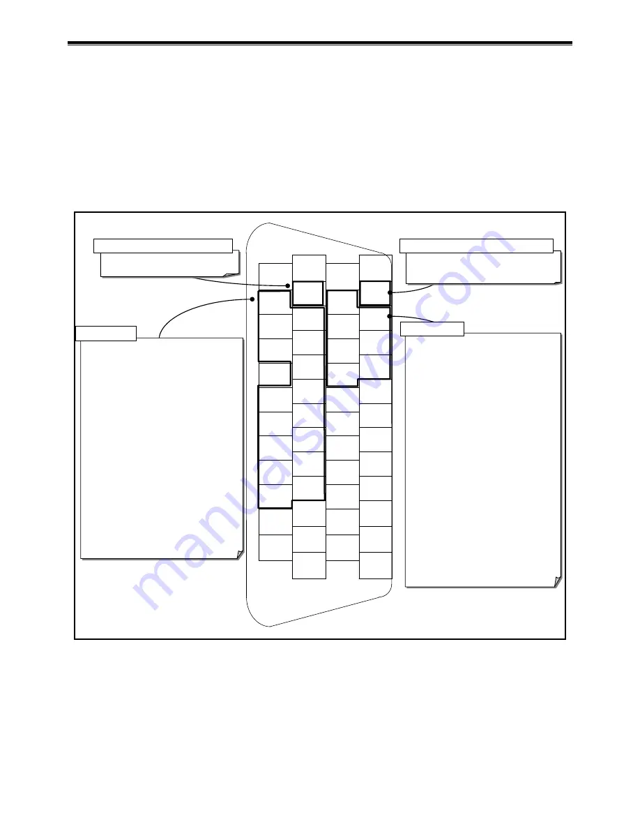
The pin-out for the CN2: Control Input/Output Signal Connector is shown in the “ Fig 2-34: Pin-out
(shipping set).”
For each port of CN2, assignment of Input/Output function can be changed. (Except for some ports)
Replace it with extended function
Change already assigned function to another port
Mask function of unused ports
Fig 2-34: Pin-out (shipping set)
1
DC24
26
COM
2
DC24
27
COM
3
PI0
(EMST)
28
PO0
(DRDY)
4
PI1
(ACLR)
29
PO1
(WRN)
5
PI2
(OTP)
30
PO2
(OTPA)
6
PI3
(OTM)
31
PO3
(OTMA)
7
PI4
(SVON)
32
PO4
(SVST)
8
PI5
(RUN)
33
PO5
(BUSY)
9
PI6
(STP)
34
PO6
(IPOS)
10
-
35
PO7
(
NEARA
)
11
PI7
(PRG0)
36
CHA
12
PI8
(PRG1)
37
*CHA
13
PI9
(PRG2)
38
CHB
14
PI10
(PRG3)
39
*CHB
15
PI11
(PRG4)
40
CHZ
16
PI12
(PRG5)
41
*CHZ
17
PI13
(PRG6)
42
-
18
PI14
(PRG7)
43
SGND
19
PI15
(JOG)
44
AIN+
20
PI16
(DIR)
45
AIN-
21
-
46
-
22
CWP+
47
-
23
CWP-
48
-
24
CCWP+
49
-
25
CCWP-
50
-
DRDY
: Driver Unit ready
WRN
: Warning
OTPA
: Travel limit detection, + direction
OTMA
: Travel limit detection, - direction
SVST
: Servo state
BUSY
: In-operation
IPOS
: In-position
NEARA : Target proximity A
NEARB : Target proximity B
ZONEA : Zone A
ZONEB : Zone B
ZONEC : Zone C
TEU
: Position error under
TEO
: Position error over
TVEU
: Velocity error under
TVEO
: Velocity error over
TVU
: Velocity under
TVO
: Velocity over
TTU
: Torque command under
TTO
: Torque command over
TJU
: Thermal loading under
TJO
: Thermal loading over
OTXA
: Travel limit ditection, ± direction
NRM
: Normal
HOME
: Home Return complete
DRDY : Driver Unit ready
NRM
: Normal
EMST : Emergency stop
EMST : Emergency stop
ACLR : Alarm clear
OTP : Travel limit, + direction
OTM : Travel limit,
– direction
SVON: Servo on
RUN : Positioning start
STP : Stop
PRG0: Internal program channel selection 0
PRG1: Internal program channel selection 1
PRG2: Internal program channel selection 2
PRG3: Internal program channel selection 3
PRG4: Internal program channel selection 4
PRG5: Internal program channel selection 5
PRG6: Internal program channel selection 6
PRG7: Internal program channel selection 7
JOG : Jogging
DIR : Jogging direction
HLD
:
Hold
ORD : Velocity override
IOFF
:
Integration off
HOS
:
Home Return start
HLS
:
Home position limit
NONE: (Set to a no-function port)
Input dedicated to safety function
Output dedicated to safety function
General input
General output
Note:1) Function in brackets is the shipping set
2) The pins with hyphen is prohibited.
PI0 and PO0 are the dedicated ports to the safety function input and output respectively.
You cannot change the function setting to the PI0 (Pin number 3: EMST input [Emergency
stop]). You may only set the logic of the connector and the stability timer to it.
You can only change the function of the PO0 (Pin number 28: DRDY output [Driver Unit
ready]) to the function NRM (normal) output. You cannot set the output logic and the stability
timer to it.
Содержание EDD Megatorque Motor
Страница 8: ... Blank Page ...
Страница 92: ...4 RS 232C Communication and USB Communication 4 16 Input the command WWC for cancellation of Multi monitor ...
Страница 146: ...6 Operation 6 38 Blank Page ...
Страница 184: ...7 Operational Function 7 38 Blank Page ...
Страница 211: ...8 More Advanced Function 8 27 ...
Страница 246: ...8 More Advanced Function 8 62 Blank Page ...
Страница 332: ...9 Details of Command and Parameter 9 86 Blank Page ...
Страница 340: ...10 Maintenance 10 8 Blank Page ...
Страница 364: ...11 Alarm and Warning 11 24 Blank Page ...


