6. Operation
— 6-11 —
6.3.2.1.
Program Operation via Control Inputs and Outputs
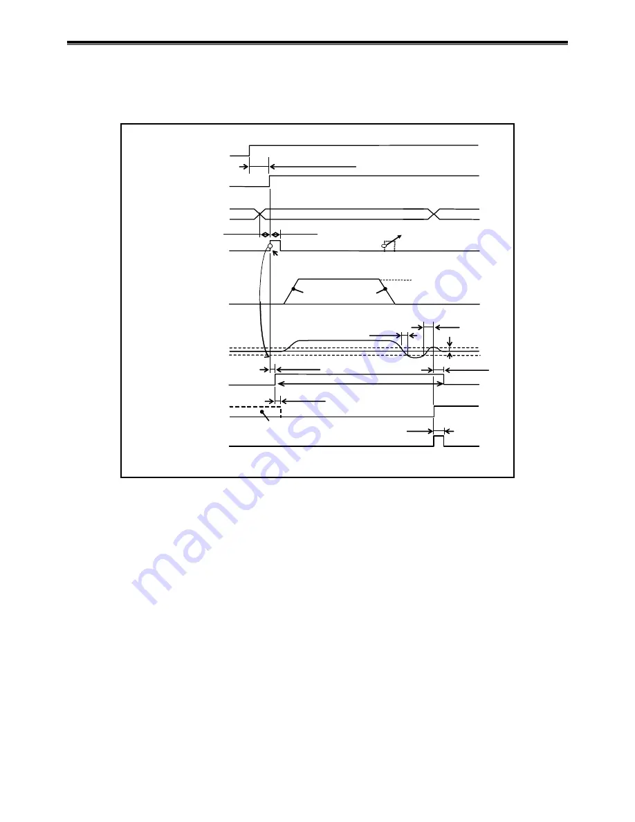
The following figure illustrates a typical procedure example of program operation.
Fig 6-6: Signal timing of program operation via control Inputs/Outputs
Residual pulse of
position error counter
溜りパルス
IN setting
Motor motion
< 100 ms
100 ms
Stability timer
(Example IS100:100ms
Max. 170 ms (*Max. 3.2 s)
ON
OFF
closed
open
SVON input
SVST output
Channel selection fixed.
MV
MB
Detection of rising edge starts
a motion.
FW data
RUN input
invalid
Min. 1 ms
1ms min.
Max. 0.5 ms
0.5 ms max.
Max. 1 ms
Channel select
(PRG0 to 7 inputs
)
RUN input
ON
OFF
closed
open
BUSY output
closed
open
closed
open
IPOS output
(FW
> 0: FIN
)
An input of the RUN signal in the
middle of positioning activates
the warning F5 (program error).
MA
Clsoed when the postion target is secured.
Open when the position target is lost.
(1)
(2)
(3)
(4)
(5)
(5)
(6)
IPOS output
(FW <
0: CFIN
)
(FW =
0: IPOS
)
*Takes 3.2 seconds to turn the Motor servo-on for the first
time after the power is turned on.
(1)
Activate the input SVON (Servo-on) to turn the Motor servo on.
(2) The output SVST (Servo state) closes when the Motor gets in the servo-on state.
(3) Select the program channel with the inputs of PRG0 to 7 (Internal program channel select).
Fix the selection 1 [ms] before the input RUN activates.
(4)
The System executes a selected channel program when the input RUN turns ON.
The positioning operation is controlled by the parameter values of MA (Rotational
acceleration), MB (Rotational deceleration) and MV (Rotational velocity).
(5) The output BUSY (In-operation) closes while the System is executing the contents of the
channel. At the same time, the output IPOS (In-position) is forcibly opened. If the input RUN is
activated while the output BUSY is closing, the warning F5 (Program error) occurs and the
Motor decelerates and stops.
(6) A positioning operation completes when the positioning error counter clears parameter values
of IN (In-position threshold) and IS (In-position stability timer) at the final stage of
positioning.
If a channel that contains no program is specified, the warning F5 (Program error) occurs.
(Refer to “11. Alarm and Warning.”)
Содержание EDD Megatorque Motor
Страница 8: ... Blank Page ...
Страница 92: ...4 RS 232C Communication and USB Communication 4 16 Input the command WWC for cancellation of Multi monitor ...
Страница 146: ...6 Operation 6 38 Blank Page ...
Страница 184: ...7 Operational Function 7 38 Blank Page ...
Страница 211: ...8 More Advanced Function 8 27 ...
Страница 246: ...8 More Advanced Function 8 62 Blank Page ...
Страница 332: ...9 Details of Command and Parameter 9 86 Blank Page ...
Страница 340: ...10 Maintenance 10 8 Blank Page ...
Страница 364: ...11 Alarm and Warning 11 24 Blank Page ...


