6-21
3.
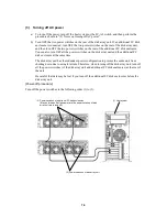
Connect the cable in accordance with the host power control unit that is to be connected with
the power control card.
–
Connection to the UPS
Connect the cable provided with the power control card. The connectors on the power
control card are UPS0 and UPS1.
–
Connection to the NX AOC
Connect the NEC Storage-AOC cable separately purchased. The connector on the power
control card is P1.
4.
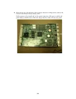
Connect the maintenance PC, and install the power control card in the disk array unit.
(For the usage of the maintenance PC, see "Appendix C Use of Maintenance PC". For the
installation method, see "1.2.3 Resource Configuration of Appendix C Use of Maintenance
PC".)
5.
Connect the disk array unit to the host power control unit.
The host power control unit (UPS or NX-AOC) to be supported depends on your
system configuration. Ask your sales representative for the host power control
unit. For the usage of the host power control unit, see the instruction manual
provided with the host power control unit.
6.
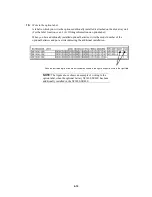
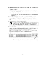
Write to the option label.
A label to which you write the options additionally installed is attached on the disk array unit.
(For the label location, see 6.1 (4) Writing information on option label.)
When you have additionally installed a power control card, write the model number of the
power control card and put a circle indicating the additional installation.
Write the last three digits of the model number as shown in the figure, and put a circle in the right field.
F
Содержание S1400 NF1400-SR40E
Страница 8: ...vii ...
Страница 9: ...viii ...
Страница 10: ...ix ...
Страница 105: ...8 21 Manufacturing number label of power supply Manufacturing number label of battery backup unit ...


