7 - 25 7 - 25
7 PARAMETER SETTINGS
POINT
(1) The network parameters other than operation setting, station No., mode and
transmission speed are also valid when the programmable controller CPU is
switched from STOP to RUN.
(2) When changing the parameters and settings of the master station or slave
station, stop the data link at the master station and then make the changes.
(3) When changing the parameters and settings of slave stations, change the
parameters of the master station according to the slave station change.
(4) For the automatic refresh parameter setting, set the start device only.
Devices are automatically assigned up to the last station number including
reserved stations and occupied stations.
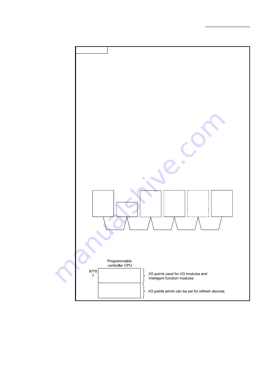
In the following system configuration example, total of remote I/O points is 96,
the total of remote register points is 12, the total of Ver.2 compatible remote I/O
points is 1184, and the total of Ver.2 compatible remote register points is 176.
Therefore, if refresh device of remote input (RX) is set to "X1000", that of
remote register (RWr) is set to "W0", that of Ver.2 compatible remote input (RX)
is set to "X1500", and that of Ver.2 compatible remote register (RWr) is set to
"W1000", the end devices will be "X105F", "WB", "X199F" and "W10AF"
respectively.
For link points of each station, refer to Section 3.2 (1).
Ver. 1
compatible
remote
device station
(occupies
2 stations)
Ver. 2
compatible
intelligent
device station
(occupies
4 stations)
octuple
Ver. 2
compatible
local station
(occupies
4 stations)
double
Master station
(X/Y00 to 1F)
Remote
I/O station
(occupies
1 station)
Station
number 8
Station
number 1
Station
number 2
Station
number 4
Station
number 9
Ver. 2
compatible
remote
device station
Reserved station
(occupies
1 station)
quadruple
(5) When setting X, Y, B, W, SB and SW as refresh devices, make setting so that
they do not overlap with the device numbers used on the other networks, etc.
(6) When setting X and Y as refresh devices, set I/O numbers higher than the I/O
numbers used for I/O modules and intelligent function modules.
Содержание L26CPU-BT
Страница 1: ......
Страница 2: ......
Страница 7: ...A 5 A 5 Disposal Precautions CAUTION When disposing of this product treat it as industrial waste ...
Страница 32: ...3 5 3 5 3 SPECIFICATIONS ...
Страница 51: ...4 2 4 2 4 PROCEDURE BEFORE OPERATION 4 ...
Страница 61: ...6 4 6 4 6 INSTALLATION AND CONNECTION ...
Страница 63: ...6 6 6 6 6 INSTALLATION AND CONNECTION 8 The connection method is shown below ...
Страница 70: ...6 13 6 13 6 INSTALLATION AND CONNECTION ...
Страница 72: ...6 15 6 15 6 INSTALLATION AND CONNECTION ...
Страница 139: ...8 33 8 33 8 FUNCTIONS ...
Страница 151: ...8 45 8 45 8 FUNCTIONS ...
Страница 243: ...11 6 11 6 11 EXAMPLE OF COMMUNICATION BETWEEN THE MASTER STATION AND REMOTE DEVICE STATIONS Set parameters as follows ...
Страница 246: ...11 9 11 9 11 EXAMPLE OF COMMUNICATION BETWEEN THE MASTER STATION AND REMOTE DEVICE STATIONS ...
Страница 311: ...13 2 13 2 13 COMMUNICATION BETWEEN THE MASTER STATION AND INTELLIGENT DEVICE STATIONS MEMO 13 ...
Страница 321: ...14 10 14 10 14 EXAMPLE OF COMMUNICATION WHEN MOUNTING MODULES ON THE HEAD MODULE ...
Страница 324: ...15 3 15 3 15 TROUBLESHOOTING 1 When the master station RUN LED is off 2 Common module check procedure ...
Страница 326: ...15 5 15 5 15 TROUBLESHOOTING To the next page ...
Страница 327: ...15 6 15 6 15 TROUBLESHOOTING To the next page ...
Страница 328: ...15 7 15 7 15 TROUBLESHOOTING ...
Страница 329: ...15 8 15 8 15 TROUBLESHOOTING 2 Troubleshooting by status logging ...
Страница 436: ...App 72 App 72 APPENDIXES 7 Operating procedure of the transmission speed test ...
Страница 439: ...App 75 App 75 APPENDIXES MEMO ...
Страница 447: ......
Страница 448: ......
Страница 449: ......


