7-26 Structure and Assembly/Disassembly
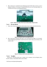
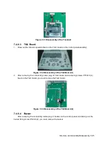
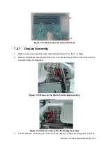
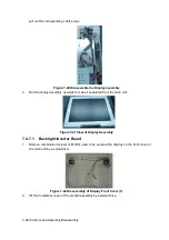
Figure 7-34 Disassembly of the Buzzer
7.4.6.5
Top cover assembly of keyboard
(
basic
)
1. Pull out the 8 TGC knobs and 4 encoder knobs upward from the control panel.
Figure 7-35 Disassemble the Control Panel (1)
2. Remove the encoder board, TGC board and trackball. The remained part is top cover
assembly of keyboard (basic).
3. Remove the buzzer, and then remove 18 PT3X10 self-tapping screws fixed on the control
panel.
Figure 7-36 Disassemble the Control Panel (2)
4. Pull out the control panel and silicon key from the keyboard cover and then dispatch them
apart, you can take out the silicon key.
Содержание Z6
Страница 2: ......
Страница 14: ......
Страница 16: ...2 2 Product Specifications Left side 9 4 7 5 6 8 ...
Страница 72: ......
Страница 119: ...Structure and Assembly Disassembly 7 35 图 7 59 Disassembly of Speaker 8 ...
Страница 120: ......
Страница 132: ......
Страница 142: ......
Страница 152: ......
Страница 168: ......
Страница 171: ...Phantom Usage Illustration B 3 ...
Страница 172: ......
Страница 173: ...P N 046 010452 00 5 0 ...


