Hardware Principle 4-5
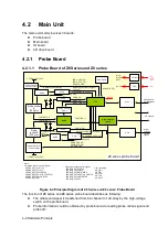
implements display interface, user's operation interface, power module controlling interface and all
kinds of Peripherals Supported interface.
Also provides system monitoring, running status of the monitor system, indicator of system status
and running status of the indicating system via LED.
Function describes as following:
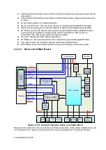
Back-end of main board connects to front-end of main board via PCIE PHY.
The USB on the lateral of Main board is the output of the CPU module.
The relevant signal in HDD of the main board is output of the CPU module.
Back-end of the main board MUL FPGA implements display ports, it also supports display
assembly, video and s-video interface of IO board.
Multifunction FPGA on the back-end of the main board is to implement the REMOTE port
on the IO panel.
Multifunction FPGA on the back-end of the main board is to implement the ECG port on the
IO panel.
The CPU module implements interfaces including USB, Ethernet and VGA on the IO
board.
System monitor circuit connects Multifunction FPGA though smbus.
Multifunction FPGA communicates with ARM by serial port to control transmission
high-voltage, and also implements ARM update by serial port.
FPGA on the power supply module implements the machine power on/off by the switch
signal.
Standby indicator, AC present indicator and working status indicator on the control panel
are output by FPGA.
The control panel implements communication with CPU module by USB.
CPU output the audio signal to the speaker on the front cover of main unit, via audio coder
and audio amplifier.
4.2.3
IO Broad
Main Board
Video
S-Video
Remote
MUL FPGA
Video
Encoder
Control
Data
VGA
USB
Ethernet
CPU
module
System
Monitor
Circuit
Status
Indicator
ECG
Figure 4-6 Principle Diagram of IO Board
IO board is connected to the main board via connectors in order to implement the user interface
function and indicate if the power is normal.
Содержание Z6
Страница 2: ......
Страница 14: ......
Страница 16: ...2 2 Product Specifications Left side 9 4 7 5 6 8 ...
Страница 72: ......
Страница 119: ...Structure and Assembly Disassembly 7 35 图 7 59 Disassembly of Speaker 8 ...
Страница 120: ......
Страница 132: ......
Страница 142: ......
Страница 152: ......
Страница 168: ......
Страница 171: ...Phantom Usage Illustration B 3 ...
Страница 172: ......
Страница 173: ...P N 046 010452 00 5 0 ...

