Structure and Assembly/Disassembly
7-27
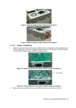
Figure 7-37 Disassemble the Control Panel (3)
7.4.7
Display Assembly
1. Remove rear cover assembly of the main unit (referring to 7.4.1 the 1
~
4 step)
2. Remove combination screws (6 M3X8) used to be secured the monitor on the front cover of
the main unit by a screwdriver.
Figure 7-38 Screws on the Right of the Display Assembly
Figure 7-39 Screws on the Left of the Display Assembly
3. Cut off cable ties connecting the main unit on the display by diagonal cutting pliers, and then
Содержание Z6
Страница 2: ......
Страница 14: ......
Страница 16: ...2 2 Product Specifications Left side 9 4 7 5 6 8 ...
Страница 72: ......
Страница 119: ...Structure and Assembly Disassembly 7 35 图 7 59 Disassembly of Speaker 8 ...
Страница 120: ......
Страница 132: ......
Страница 142: ......
Страница 152: ......
Страница 168: ......
Страница 171: ...Phantom Usage Illustration B 3 ...
Страница 172: ......
Страница 173: ...P N 046 010452 00 5 0 ...


