9-4 Care and Maintenance
Trackball is one of important interface parts, which are embedded into the main unit keyboard, and
part of which is exploded to be operated by users in order to implement variety of module’s control
functions. Trackball is one of the most using frequency of input assemblies on the whole operation
panel, and the trackball similar to a multi-directory caster can rotate in every direction drived
manually, due to the feature, gas or dust can enter into module internal easily, as a result,
contamination of lens would lead to the failure of the trackball.
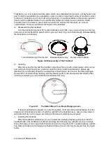
a) Disassembling the trackball:
Turn the trackball ring about 35°counterclockwise until it lifts, now, you would remove the ring
and pull out the trackball with pl
astic cloth if you can’t hold it by your hands directly. Disassembling
the trackball is as following:
Turn trackball ring 35°to the left Disassemble the ring Remove the trackball
Figure 9-2 Disassembly of the Trackball
b) Cleaning
After removing the ring and the trackball, wipe down the lens with a clean paper until you can
see nothing in the groove zoom, and then clean the other contaminant material , please pay
attention to your intensity adopted on wiping dust of bead down, as shown in the following figure.
Power-off is not need during cleaning, and maintenance effect can be experienced directly. After
cleaning completely, you can install the trackball and the ring.
Figure 9-3
The Sketch Map of
Len, Bead, Dragon groove
If liquid is accidentally sprayed on or into the system, most of which could discharge from the
dragon port of trackball, but some of which would left in the trackball cover, now you may clean it
with clean soft dry cloth or paper according to the above maintenance procedure.
c) Installing the trackball
After the trackball maintenance, you can restore the installing following procedure: Put the
trackball back in the trackball mechanism and align the clamping ring with the top cover notches.
Press the bulges on the ring with both hands and turn the ring about 35° counterclockwise until the
ring clicks and locks. As the bulges are flush with the top cover, the ring is secured. See the figure
below.
Содержание Z6
Страница 2: ......
Страница 14: ......
Страница 16: ...2 2 Product Specifications Left side 9 4 7 5 6 8 ...
Страница 72: ......
Страница 119: ...Structure and Assembly Disassembly 7 35 图 7 59 Disassembly of Speaker 8 ...
Страница 120: ......
Страница 132: ......
Страница 142: ......
Страница 152: ......
Страница 168: ......
Страница 171: ...Phantom Usage Illustration B 3 ...
Страница 172: ......
Страница 173: ...P N 046 010452 00 5 0 ...


