Hardware Principle 4-1
4
Hardware Principle
4.1
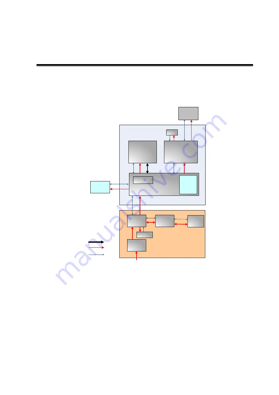
General Structure of Hardware System
DC-DC
board
AC IN
Battery
connecting
board
Battery
AC-DC
board
Main
board
Probe
board
IO board
Fan
Charge/
discharge
Fan
Monitor
Control panel
Power supply
Comm&control
Ultrasound signal
CPU
module
4D drive
board
Figure 4-1
Schematic Diagram of System
As a portable black-and-white ultrasonic product
,
the system supports two probe slots.
The detailed
structure of hardware system is in the figure above, and they can be divided into 4
modules:
Main unit module
Power supply module
Monitor module
Control panel module
The detailed description of 4 modules will be in the following:
Содержание Z6
Страница 2: ......
Страница 14: ......
Страница 16: ...2 2 Product Specifications Left side 9 4 7 5 6 8 ...
Страница 72: ......
Страница 119: ...Structure and Assembly Disassembly 7 35 图 7 59 Disassembly of Speaker 8 ...
Страница 120: ......
Страница 132: ......
Страница 142: ......
Страница 152: ......
Страница 168: ......
Страница 171: ...Phantom Usage Illustration B 3 ...
Страница 172: ......
Страница 173: ...P N 046 010452 00 5 0 ...


