4-12 Hardware Principle
No.
Power
description
Support circuit module or function
Remarks
3 +5V
HDD, Control panel, Front-end of main board, Probe board
4 -5V
Front-end of main board
5 5Vst
CPU module
6 VDD
Front-end of main board, Back-end of main board, Display
7 1V2
Back-end of main board (FPGA core voltage)
8 1V8A
Front-end of main board (receiving chip)
9 1V8
Back-end of main board ( video encoder, FPGA IO voltage ,
DDR2)
10 2V5
Back-end of main board ( video encoder, FPGA IO voltage)
11 +95V
Probe board (high-voltage switch)
12 -95V
Probe board (high-voltage switch)
13 +PHV
Transmitting high-voltage
14 -PHV
Transmitting high-voltage
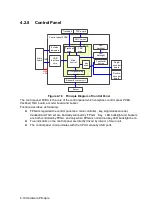
4.3.2
System Power-on Control
CPU
module
PWR_BTN_N
D12V
SUS_S3_N
SUS_S4_N
CPU_PWR_BTN_N
PWR_OK_N
5VSTB
power
supply
manag
ement
FPGA
AC-DC
board
19V
AC in
place
signal
DC-DC
board
Main
board
Control
panel
PWR_12V_EN_N
PWR_5VSTB_EN_N
PWR_5VSTB_OK_N
PWR_12V_OK_N
AC_IN_STATUS_N
3V3STB
Figure 6-12 Diagram of System Power-on Supported Circuit
Related controlling signal comment:
No
Controlling signal
Description
Remarks
1
PWR_BTN_N
The pulse generated by the power button on the control
panel is sent to CPU module through power
management FPGA, to power on the system.
Содержание Z6
Страница 2: ......
Страница 14: ......
Страница 16: ...2 2 Product Specifications Left side 9 4 7 5 6 8 ...
Страница 72: ......
Страница 119: ...Structure and Assembly Disassembly 7 35 图 7 59 Disassembly of Speaker 8 ...
Страница 120: ......
Страница 132: ......
Страница 142: ......
Страница 152: ......
Страница 168: ......
Страница 171: ...Phantom Usage Illustration B 3 ...
Страница 172: ......
Страница 173: ...P N 046 010452 00 5 0 ...


