- 1-4 -
Name
Function
1
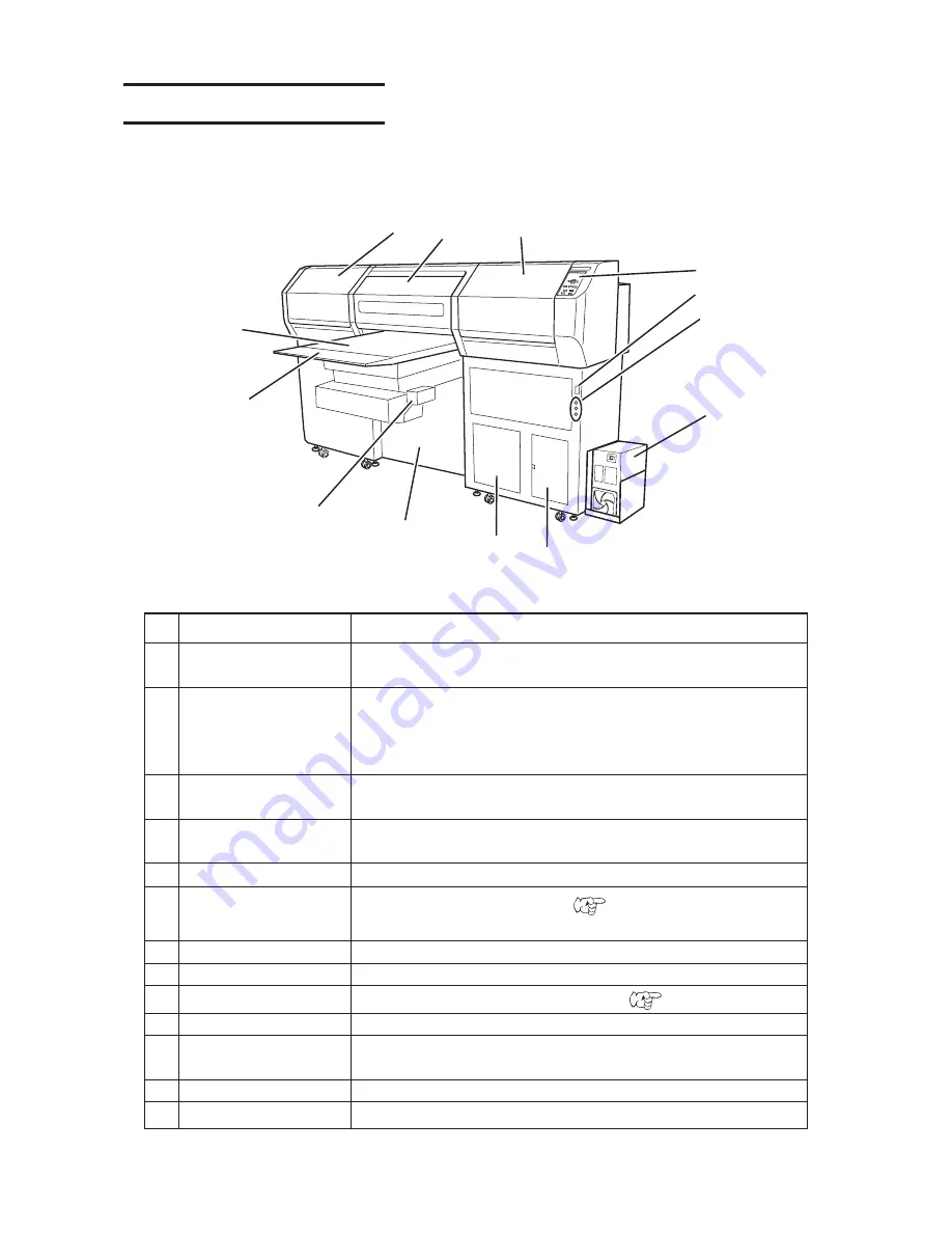
Left maintenance cover
Position for standby during printing. Equipped with a flushing tray
and opened and closed during maintenance.
2
Front cover
It is opened when setting media or taking a corrective measure
against a media jam. Even if the power switch is off, keep the
front cover closed to perform the ink clogging preventive opera-
tion.
3
Right maintenance cover
Equipped with a capping station and opened and closed during
maintenance.
4
Operation panel
This panel has the operation keys required for operating the
device and the LCD for displaying set items, etc.
5
Power switch
It turns on/off the power to the device.
6
UV lamp status indicator
Indicates the UV lamp status. (
P.1-13)
Error (red)/UV lamp OFF, then cooling (orange)/enabled (green)
7
UV unit
Supplies power for the UV lamp.
8
Waste ink tank
Waste ink gathers in this tank.
9
Water heater
Keeps ink at appropriate temperature. (
P.3-8)
10
Blower unit
This allows a media to be pneumatically picked on the praten.
11
Sub-panel
Provides functions for moving the table up/down, turning the
blower ON/OFF and copying.
12
UV light-resistant panel
Blocks light leaked from the UV lamp.
13
Table
Moves back and forth when performing printing.
1
Configuration and function
The front
2
4
3
5
6
7
8
9
10
11
12
13
Содержание UJF-605C
Страница 2: ......
Страница 68: ...2 30...
Страница 88: ...3 20...
Страница 104: ...4 16...
Страница 148: ...A 6...
Страница 153: ......
Страница 154: ...Printed in Japan MIMAKI ENGINEERING CO LTD 2012 IT FW 3 2...

