background image

Lucent Technologies Lineage

®

 2000 100A Ferroresonant Rectifier J85503A-1

6 - 2  Testing 

 Issue 6  October 1998

Tools and Test 
Equipment

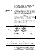
The following items are needed for testing the rectifier.

DMM (Digital Multimeter) Fluke 8060A or equivalent 
meter having 0.02 percent accuracy on dc scale

Battery Plant Simulator Test Set, customer constructed, or 
equivalent (see Figure 6-1)

DC dummy test load, 26-volt (24-volt rectifier) or 52-volt 
(48-volt rectifier) with adjustment to provide a load of 120 
amperes, 120 percent of the rectifier's rating

Jeweler's screwdriver for adjusting potentiometers

Straightened paper clip inserted in eraser of wooden pencil

Battery Plant

Simulator Test

Set

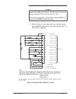
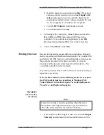
The Battery Plant Simulator Test Set is a convenient tool used to 
isolate communication troubles between the plant controller and 
the rectifier. It simulates the plant controller relative to receiving 
signals from, and sending signals to, the rectifier. If there is a 
problem and the rectifier works properly with the test set, the 
problem is either at the controller or in the interface wiring (plant 
cable). Figure 6-1 shows how to construct a test set and cable.

Test Load

Connection

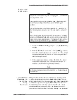
The following procedures are used to connect a test load when 
called for in a test or other procedure. Refer to the rectifier 
control panel in Figure 2-5. Test load connections are made on 
the internal bus of the rectifier. Therefore, to isolate the rectifier 
from the batteries and plant bus, the rectifier DC Output circuit 
breaker must be left open (off) while the test load is connected.

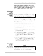
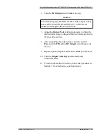
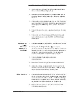
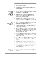
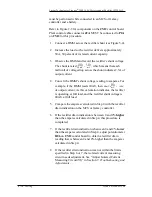
1. At the ac service panel, remove ac power to the rectifier.

2. Turn off (down) the rectifier DC Output circuit breaker.

3. Disconnect J2A from CM2 by unlatching first, then 

pulling the cable connector.

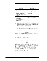
Warning

Do not turn the DC Output circuit breaker ON, close an 
external charge circuit breaker, or install an external charge 
fuse until told to do so.

Содержание Lineage 2000

Страница 1: ...Lineage 2000 100 Ampere 60 Hertz Ferroresonant Rectifier J85503A 1 Product Manual Select Code 169 790 119 Comcode 107021818 Issue 6 October 1998 1998 Lucent Technologies ...

Страница 2: ......

Страница 3: ...echnologies Lineage 2000 100 Ampere 60 Hertz Ferroresonant Rectifier Notice Every effort was made to ensure that the information in this document was complete and accurate at the time of printing However information is subject to change 1998 Lucent Technologies All Rights Reserved Printed in U S A ...

Страница 4: ......

Страница 5: ... Description Overview 2 1 Ferroresonant Technology 2 1 Standard Features 2 2 Additional Features 2 4 Circuit Modules 2 5 Front Panel Controls and Indicators 2 10 Alarm and Control Flow 2 12 Physical Thermal and Electrical Specifications 2 13 3 Ordering Information Options 3 1 4 Safety Admonishments 4 1 Safety Statements 4 1 Precautions 4 2 Warning Statements and Safety Symbols 4 4 5 Installation I...

Страница 6: ...ging Optional 5 17 6 Testing Introduction 6 1 Precautions 6 1 Tools and Test Equipment 6 2 Battery Plant Simulator Test Set 6 2 Test Load Connection 6 2 Initial Conditions for Testing Off Line 6 4 Testing Off Line 6 6 Startup 6 6 Regulation NL FL Test Off Line 6 7 Rectifier Failure Alarm Fuse Alarm Test Off Line 6 7 Current Limit Test Off Line 6 7 Phase Failure Test Off Line 6 8 Backup High Voltag...

Страница 7: ...rcuit VI 7 8 Adjust Current Limit 7 10 Restore Rectifier to Service 7 10 8 Spare Parts and Replacement Procedures Ordering Circuit Modules 8 1 Handling Circuit Modules 8 1 Electrostatic Discharge 8 2 Modifying the CM1 Option Board 8 3 Spare Fuses 8 4 Replacing Circuit Modules 8 4 Replace CM1 Option Board 8 4 Replace CM2 Control Board 8 5 Replace CM3 Digital Meter Board 8 7 General Considerations f...

Страница 8: ...J85503A 1 4 Table of Contents Issue 6 October 1998 DC Inductors L3 or L4 8 15 DC Capacitors C1 C2 or C3 C4 8 16 Main Transformers T1 or T2 8 17 Rectifier Diode Test and or Replacement 8 17 Heat Shrink Removal 8 19 Disconnecting a Rectifier 8 19 9 Product Warranty ...

Страница 9: ...ure 2 4 Partial Sketch of CM3 Digital Meter Board 2 9 Figure 2 5 Control Panel on the J85503A 1 Rectifier 2 10 Figure 2 6 Signal Flow between Rectifier and Lucent Technologies Controller 2 13 Figure 5 1 Four Views of the J85503A 1 Rectifier 5 6 Figure 5 2 Front View of J85503A 1 Rectifier with Door Open 5 7 Figure 5 3 AC Input Components Mounted on the Upper Left Side of the J85503A 1 Rectifier Be...

Страница 10: ......

Страница 11: ...5503A 1 Rectifier 3 2 Table 5 A AC Input Requirements 5 3 Table 5 B DC Output Requirements 5 4 Table 5 C AC Voltage Conversion 5 14 Table 5 D Rectifier Control Settings for Initial Battery Charge 5 18 Table 6 A Rectifier Control Settings for Testing Off Line 6 4 Table 6 B Test Set Connections 6 6 Table 6 C Rectifier Control Settings Prior to Testing On Line 6 12 Table 7 A Troubleshooting 7 3 Table...

Страница 12: ...0A Ferroresonant Rectifier J85503A 1 2 List of Tables Issue 6 October 1998 Table 8 D Torque and Minimum Yield Strength for Mechanical Connections Using Hex Head Cap Screws 8 10 Table 8 E Minimum Torque for all Electrical Connections 8 11 ...

Страница 13: ...rectifier is an excellent choice for any telecommunications battery plant The J85503A 1 rectifier can be used with a Lineage 2000 battery plant older vintage Lucent Technologies battery plants or any commercial battery plant With certain options it can also operate off battery Customer Training Lucent Technologies offers customer training on many Power Systems products For information call 1 972 2...

Страница 14: ...your technical questions and assist in troubleshooting problems For other customers worldwide contact your local field support center or your sales representative to discuss your specific needs Product Repair and Return Repair and return service is provided for Lucent Technologies customers around the world For customers in the United States Canada Puerto Rico and the US Virgin Islands call 1 800 ...

Страница 15: ...ology The J85503A 1 rectifier is a member of the Lucent Technologies family of Lineage 2000 rectifiers Like all the rectifiers in the family it represents a significant advancement in efficiency space savings and serviceability The rectifier uses the electronically controlled closed loop ferroresonant technology developed by Lucent Technologies This technology provides excellent output regulation ...

Страница 16: ...ntrol are mounted on replaceable circuit modules Front access to the circuit modules simplifies replacement or adjustment if required Standardized modules simplify parts inventory resulting in lower costs and better equipment availability The rectifier is contemporary in appearance with a blue cabinet white front door and flat black control panel The rectifier can be used in a plant with or withou...

Страница 17: ...om an independent voltage source in accordance with Bellcore standards Output current limit The rectifier provides a constant output voltage up to its rated output current at which point it provides constant current When the output current tends to increase above the rated output the current limit circuit overrides the voltage regulating signal and limits the output current of the rectifier Back u...

Страница 18: ... feature that is compatible with most controllers If a rectifier shuts down due to the external selective high voltage shutdown most controllers try at least once to restart it automatically Remote sense leads These leads permit remote regulation of the rectifier TR This signal Transfer Rectifier remotely shuts down the rectifier Additional Features Dynamic Response For any step load change of 10 ...

Страница 19: ...rcuitry common to several rectifiers in the Lineage 2000 rectifier family The factory provides the options required for each application by removing certain wire straps and resistors from the CM1 board The factory modification of CM1 is complete when the board is installed in the rectifier However ordered spare or replacement CM1 boards have not been modified The customer must make this modificati...

Страница 20: ...contains a triac thyristor snubber network Refer to schematic drawing SD 82605 01 for further information Caution Circuit modules must not be connected or disconnected with voltages present or equipment damage may occur See Replacing Circuit Modules in Section 8 Spare Parts and Replacement Procedures for how to replace circuit modules Figure 2 1 Location of Circuit Modules CM3 Digital Meter Board ...

Страница 21: ...ent Technologies Lineage 2000 100A Ferroresonant Rectifier J85503A 1 Issue 6 October 1998 Product Description 2 7 Figure 2 2 CM1 Option Board Showing White Test Clip Connection and Removable Straps K and M ...

Страница 22: ...ucent Technologies Lineage 2000 100A Ferroresonant Rectifier J85503A 1 2 8 Product Description Issue 6 October 1998 Figure 2 3 CM2 Control Board Showing Test Clip Connections and Other Component Details ...

Страница 23: ...Lucent Technologies Lineage 2000 100A Ferroresonant Rectifier J85503A 1 Issue 6 October 1998 Product Description 2 9 Figure 2 4 Partial Sketch of CM3 Digital Meter Board ...

Страница 24: ... labels that appear on the control panel or inside the rectifier The digital Output meter displays 1 the rectifier output current when the selector switch is in the Amps position 2 the rectifier output voltage when the selector switch is in the Rect V position and 3 the plant battery voltage when the selector switch is in the Batt V position The default display is rectifier output current Table 2 ...

Страница 25: ... RFA LED lights and a signal is sent to the plant controller if the rectifier fails because of external or internal high voltages a blown fuse or an internal unbalance The Rect Test switch provides a manual test of the rectifier regulation by simulating a full load FL or no load NL condition Operating the switch raises or lowers the output voltage setting of the rectifier by 0 25 volt when on batt...

Страница 26: ...and Control Flow The J85503A 1 100 ampere rectifier is typically installed in a battery plant that is monitored and controlled by a Lucent Technologies Lineage 2000 controller The rectifier generates various monitoring and alarm signals and in this type of installation sends them to the controller for processing and subsequent action The action may be local or remote alarm indications or control s...

Страница 27: ...wn TR Rectifier Current Capacity TP Rectifier Failure Alarm RFA Rectifier Restart RS Rectifier Current Drain VI Rectifier Efficiency Algorithm TRH Phase Failure Alarm PHA Plant Control Cable Assembly is manufactured by Lucent Technologies and must be ordered separately See Lineage 2000 Battery Plant documentation for details Remote Regulation R R To Plant Controller Plant Control Cable Assembly Ta...

Страница 28: ...ble 2 B Physical and Thermal Specifications of the J85503A 1 Rectifier Output DC 24V Output DC 48V Measured at 28 Vdc for 24 volt rectifiers and at 54 Vdc for 48 volt rectifiers Table 2 D Output Specifications for the J85503A 1 Rectifier Nominal Rectifier amps volts Output Range amperes Output Range dc volts Minimum Efficiency at Full Load percent Minimum Power Factor at Full Load AC Ripple mV pea...

Страница 29: ...ltages Lists 10 and 15 or 16 are also always required to provide a digital meter and additional output filtering Emergency or end cells List 17 are additional cells which are either manually or automatically connected in series with the battery in the event of low battery voltage such as occurs during an ac power failure The use of emergency cells maintains prescribed voltage limits during battery...

Страница 30: ...48 3 240 24 4 240 48 5 480 24 6 480 48 Always Required List Number Provides 10 Digital meter 15 Additional output filtering on 24V rectifiers 16 Additional output filtering on 48V rectifiers Optional List Number Provides 17 Emergency EM cell charging capability 18 Chassis assembly for mounting rectifier in J86658A 3820 power conditioning cabinet B Circuit breaker in positive output lead Negative G...

Страница 31: ... restricted access areas dedicated equipment rooms equipment closets or the like in accordance with articles 110 16 110 17 and 110 18 of the U S National Electric Code NEC ANSI NFPA No 70 and pursuant to applicable local codes This equipment must not be installed over combustible surfaces This equipment is to be used in controlled environments an area where the humidity is maintained at levels tha...

Страница 32: ...r s and all local requirements for proper connections All national and local rules and regulations are to be followed when making field connections Torque electrical connections to the values specified on labels or in the product documentation Precautions When working on or using this type of equipment follow these precautions This unit must be installed serviced and operated only by skilled and q...

Страница 33: ...r can be disconnected at the plant charge battery and charge ground buses DC capacitors may be charged even with power disconnected from the rectifier If filter capacitor fuses have blown capacitors will be charged Always check all of the dc capacitor terminals observe polarity with a voltmeter before performing this procedure and discharge capacitors safely if necessary Wait at least 5 minutes af...

Страница 34: ... covers avoid contacting any circuits Use gloves when handling thermally hot components inside the rectifier Transformers are very hot after sustained operation Warning Statements and Safety Symbols This symbol identifies the need to refer to the equipment instructions for important information This symbol or equivalent is used to identify the presence of hazardous ac mains voltage This symbol or ...

Страница 35: ...ed metal objects Follow safety precautions This symbol is used to identify the need for safety glasses and may sometimes be accompanied by some type of statement for example Fuses can cause arcing and sparks Risk of eye injury Always wear safety glasses This symbol is used to identify the presence of a hot surface It may also be accompanied by a statement explaining the hazard A symbol like this w...

Страница 36: ......

Страница 37: ... carefully read and follow the admonishments as they are presented throughout this documentation Preparing for Installation Location of the J85503A 1 rectifier and associated equipment must conform to the specific plans of each Lineage 2000 plant installation Physical thermal and electrical specifications are given in Section 2 These specifications must be considered in the plans for any installat...

Страница 38: ...onment is another factor in selecting a location for the J85503A 1 The maximum heat exhausted by each 24 and 48 volt rectifier is approximately 1300 BTU hr and 2050 BTU hr respectively The rectifiers use free convective cooling where cooler air enters the cabinet through perforations in the front door and is exhausted through perforations in the top cover A minimum of 23 inches in front and 2 inch...

Страница 39: ...g the mechanical connection provided Discard this connection if you prefer the T B2 crimp connection also provided See note 61 on J drawing J85503A 1 1 BUSSMANN is a trademark of the BUSSMANN Company 2 T B is a trademark of the Thomas Betts Company Table 5 A AC Input Requirements List Volts Amps Line Fuse Type Rating Input Circuit Breaker Size amps Number of Input Wires Gauge Armored Cable Trade S...

Страница 40: ...s The following tools are required for installing rectifiers Material handling equipment to unload rectifiers at site remove them from shipping containers and place them in final positions Common electrician s hand tools including jeweler s screwdriver electrical tape wire cutters and strippers 14 AWG to 2 AWG wire Proper crimping tools and dies for connectors used in the installation Table 5 B DC...

Страница 41: ...ed exterior of rectifier for shipping damage 5 With rectifier lying on its back open the front door and visually inspect for shipping damage 6 If material is damaged contact shipping company and process claims form 7 Verify that the main ac voltage at the distribution panel agrees with the List options specified on the label inside the front door of the rectifier If it does not agree two possible ...

Страница 42: ... 1 5 6 Installation Issue 6 October 1998 provided in Converting AC Voltage in Section 5 The procedure for placing the DC Output circuit breaker CBA1 in the opposite output bus is described in Converting DC Output Polarity Figure 5 1 Four Views of the J85503A 1 Rectifier ...

Страница 43: ...Lucent Technologies Lineage 2000 100A Ferroresonant Rectifier J85503A 1 Issue 6 October 1998 Installation 5 7 Figure 5 2 Front View of J85503A 1 Rectifier with Door Open ...

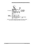
Страница 44: ...logies Lineage 2000 100A Ferroresonant Rectifier J85503A 1 5 8 Installation Issue 6 October 1998 Figure 5 3 AC Input Components Mounted on the Upper Left Side of the J85503A 1 Rectifier Behind the Protective Shield ...

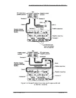
Страница 45: ...Lucent Technologies Lineage 2000 100A Ferroresonant Rectifier J85503A 1 Issue 6 October 1998 Installation 5 9 Figure 5 4 Output Polarity Conversion and Component Detail on Bus Bar Assembly ...

Страница 46: ...ier Install AC Power Cables Use Figures 5 1 5 2 and 5 3 as references for this section 1 Using site drawing information locate the exact position specified for the rectifier DANGER Follow procedures in the order given to minimize exposure to voltages up to 530 volts ac and 60 volts dc Remove all jewelry and use insulated tools when working on or near electrically live parts Use a voltmeter to insu...

Страница 47: ...s for Lists 5 and 6 to 20 in lbs Torque phase connections to 35 in lbs for Lists 1 4 7 Verify that the branch circuit breaker to the rectifier in the ac service panel is off or fuses are removed Reenergize ac service panel Tag branch circuit breaker or fuse holders to inform others not to close turn on the breaker or insert fuses If the branch circuit all phase leads plus the frame ground is prote...

Страница 48: ...s See Figure 5 2 10 Remove tape or insulation from connector at other end of output cable and terminate connector on hot charge bus bar Install Plant Control Cable Assembly for a Lucent Technologies Controller The Plant Control Cable Assembly has a 24 pin or 16 pin connector on one end and a 40 pin connector on the other end The 24 pin or 16 pin end terminates on the battery plant controller and t...

Страница 49: ... For a Galaxy controller locate the J85501F 1 L 31 MCS compatible RIM Rectifier Interface Module mounted on the rear of the controller backplane Each RIM position A B or C has 8 rectifier ports For Expandable Controlled System XCS plants open the front panel and thread the control cable through the hole in the wall of the controller There are six 16 pin connectors labeled Rect 1 through Rect 6 For...

Страница 50: ... This procedure MUST be performed ONLY on a rectifier completely disconnected from the battery and plant bus AND with ac power disconnected at the ac service panel Table 5 C AC Voltage Conversion Input Line Voltage Main Transformer K1 Contactor Connections Needed Main Transformer Leads to be Removed from K1 and Insulated Auxiliary Transformer T3 Connections Needed via Fast On Terminal Strip on T3 ...

Страница 51: ... for 208 Vac or 3 5 and 1 for 240 Vac Pull these wires up to K1 4 Push the wires removed from K1 in Step 1 down to where the alternate voltage wires were and bundle them 5 Install the three alternate voltage wires to the K1 contactor as specified in the second column of the table Jumper Connections on Fast On Terminal Strip 6 Note that permanent connections to the terminal strip are on contacts A1...

Страница 52: ...B from terminal B Reconnect this end to terminal A 3 Remove the end of Cable C from terminal C Reconnect this end to terminal D 4 Install Cable A removed in Step 1 between terminal B and terminal C Cable A may have to be positioned other than the way shown in order to reach between B and terminal C 5 The wiring should now appear as in the lower drawing of Figure 5 4 Indicate by stamping on the ins...

Страница 53: ...by removing the List B stamping Initial Battery Charging Optional Initial battery charging should be planned as part of the plant installation If initial battery charging is desired with the current rectifier installation the rectifier should be tested before following this procedure see Section 6 Testing The J85503A 1 rectifier is capable of supplying a new battery string with its initial charge ...

Страница 54: ...crewdriver to turn the Output Volts Adj potentiometer clockwise until the digital meter reads approximately battery voltage typically 26 volts for 24 volt plants or 52 volts for 48 volt plants Table 5 D Rectifier Control Settings for Initial Battery Charge Controls Position Status Rectifier Power Switch Off down Rectifier DC Output circuit breaker Off down Output Volts Adj potentiometer Fully coun...

Страница 55: ...completing the initial charge turn the rectifier Power switch Off and the DC Output circuit breaker off down 9 Replace option straps K and M on the CM1 option board 10 Turn the Output Volts Adj potentiometer fully counterclockwise 11 To restore the rectifier to service follow the procedure in Section 7 Troubleshooting and Adjustments Caution In the following step DO NOT set the rectifier output vo...

Страница 56: ......

Страница 57: ...d for testing off line See Tools and Test Equipment later in this section for a description of these items For troubleshooting and diagnostic procedures refer to Section 7 Troubleshooting and Adjustments Those unfamiliar with the function of rectifier controls and indicators should read Section 2 Product Description Precautions When working on power systems observe safety precautions in Section 4 ...

Страница 58: ... controller relative to receiving signals from and sending signals to the rectifier If there is a problem and the rectifier works properly with the test set the problem is either at the controller or in the interface wiring plant cable Figure 6 1 shows how to construct a test set and cable Test Load Connection The following procedures are used to connect a test load when called for in a test or ot...

Страница 59: ...34 of CM2 To P2A 37 of CM2 To P2A 31 of CM2 To P2A 27 of CM2 To P2A 2 of CM2 Blue Test Clip See Note White Test Clip Black Test Clip To P2A 12 of CM2 BAT R2 R1 2150 2150 1 WATT 2150 1 WATT 2150 1 WATT 2150 1 WATT R3 R4 R5 MAN 1 1 1 1 1 2 2 2 2 2 3 3 3 1 1 1 2 2 2 F1 F2 1 1 3 1 1 3 TR PWR HV RS RFA TRH PH MAN RFA TRH PH or LOA DPG TR48 HV48 RS RSR APG R R V V 27V Return Note Use 24 AWG multiconduct...

Страница 60: ...ks Before the REG fuse is installed in the plant controller verify that battery voltage is not present between the rectifier output charge terminal and dc output return see Figure 5 4 Install the regulation REG fuse associated with the rectifier in the plant controller Check for battery voltage between pins 27 and 2 of control cable connector J2A The J2A connector is at the rectifier end of the pl...

Страница 61: ...d If the plant is equipped with an MCS controller again on J2A check for 15 20 volts dc between pins 35 and 31 Pin 35 should be positive with respect to pin 31 4 Place the Battery Plant Simulator Test Set Figure 6 1 at a convenient location near the rectifier Connect J2A on the other end of the cable from the test set to connector P2A on the CM2 control board mounted on the inside of the front doo...

Страница 62: ...he rectifier The PWR lamp on the test set should light brightly If it does not light properly check the connection of the two small red and black clip leads They may be reversed or otherwise incorrectly connected These leads provide the operating voltages in the test set and the red lead should be approximately 27 volts dc with respect to the black lead 2 The PWR lamp should remain lit during the ...

Страница 63: ...the test meter and move the Rect Test switch to NL In the NL position the voltage should drop between 0 3 and 0 6 volt 2 Repeat Step 1 with the Rect Test switch in the FL position The voltage should increase between 0 1 and 0 4 volt Rectifier Failure Alarm Fuse Alarm Test Off Line 1 Insert a piece of bare wire or the end of a paper clip into a pencil eraser Holding the pencil insert the wire next ...

Страница 64: ...nd Adjustments 4 Increase the load to 109 111A 110 1 percent Vout should be below 51 58 volts 48 volt rectifier 25 79 volts 24 volt rectifier If not see Adjust Current Limit in Section 7 Troubleshooting and Adjustments 5 Decrease the load to 96 98A 96 to 98 percent of the rectifier rating Observe that Vout is greater than 52 03 volts 48 volt rectifier 26 01 volts 24 volt rectifier Phase Failure Te...

Страница 65: ...it breaker is On turn it Off down 2 Slowly turn the Output Volts Adj potentiometer clockwise until the rectifier shuts down This should occur between 29 and 31 25 volts 24 volt rectifier or between 58 and 62 5 volts 48 volt rectifier The RFA on the rectifier and the RFA on the test set should light 3 Turn the Output Volts Adj potentiometer counterclockwise 4 Restart the rectifier using the RS swit...

Страница 66: ...0 amperes 50 of its rated current capacity 2 Connect a DMM set on the dc millivolt scale across the rectifier s 125A 50mV shunt 3 Observe the DMM and record the rectifier s shunt voltage The shunt is rated 125A 50mV 2 5A mV which means that each millivolt of voltage drop across the shunt indicates 2 5A of output current 4 Convert the DMM shunt voltage reading to amperes For example if the DMM read...

Страница 67: ...of total plant testing restore the rectifier to service by following the procedures described under Restore Rectifier to Service in Section 7 Troubleshooting and Adjustments If this is part of total plant testing leave the plant control cable disconnected at this time until directed to reconnect it as part of another plant procedure Bringing Rectifier On Line The following steps bring the rectifie...

Страница 68: ...sition Status Associated ac circuit breaker or fuses at the ac service distribution panel Off or fuses removed and holders tagged Out of Service Rectifier Power switch Off down Rectifier DC Output circuit breaker Off down Output Volts Adj potentiometer Fully counterclockwise Associated REG fuse in plant controller Removed Warning DO NOT turn on the DC Output circuit breaker without first turning t...

Страница 69: ...re different procedures although most tests can be performed in either situation The Control TR and Selective HVSD Tests are omitted from this section because these signals originate in the plant controller or a remote location and the test procedure depends on that device See your plant controller product manual If you have just tested the rectifier off line it is not necessary to repeat the test...

Страница 70: ...ert a piece of bare wire or the end of a paper clip into a pencil eraser Holding the pencil insert the wire next to the alarm indicator of the V fuse on the control panel Note that the rectifier shuts down and the RFA lamp on the control panel lights 2 Turn the Power switch Off then back On The RFA light should go off 3 Repeat Steps 1 and 2 at the V fuse Notes This procedure causes the rectifier t...

Страница 71: ...he procedure is required only when CM2 is installed as part of a Lineage 2000 MCS Microprocessor Controlled System or Galaxy system and when the output current reading on the rectifier does not agree to within 2 5 percent of the MCS or Galaxy controller reading This procedure Notes Adjust the current limit only after verifying that a current limit circuit problem exists There must be two or more r...

Страница 72: ...le if the DMM reads 40mV then of output current As this calculation indicates the rectifier is operating at full load and the rectifier shunt voltage is 40mV at full load 5 Compare the amperes calculated in Step 4 with the rectifier drain indication on the MCS or Galaxy controller 6 If the rectifier drain indication is between 0 and 2 higher than the amperes calculated in Step 4 this procedure is ...

Страница 73: ... off the ac at the service panel and reconnect the input lead 7 Turn on the ac at the service panel The rectifier should restart Backup High Voltage Shutdown HVSD Test On Line If the DC Output circuit breaker is on turn it off down 1 Connect the DMM to the rectifier output terminals see Figure 5 2 2 Slowly turn the Output Volts Adj potentiometer clockwise until the rectifier shuts down This should...

Страница 74: ...n 20 mV x 2 5A mV 50A of output current 5 Compare the amperes calculated in Step 4 with the digital display of the meter while the switch is in the AMPS position 6 If the digital display is between 2 2A than the amperes calculated in Step 4 this procedure is completed 7 If the rectifier drain indication is not as indicated in Step 6 calibrate the CM3 card via its R15 potentiometer as specified in ...

Страница 75: ...voltage the rectifiers must be on line with plant cables connected and REG fuses installed in the plant controller or a remote bay Adjust Rectifiers Individually The fastest way to adjust a group of rectifiers to float voltage is to adjust them individually turning each one off after adjustment and turning them all on after the last adjustment In order to use this method however the load requireme...

Страница 76: ...age perform the following a If the voltage is too high turn the Output Volts Adj potentiometer counterclockwise on the rectifier with the highest output current b If the voltage is too low turn the Output Volts Adj potentiometer clockwise on the rectifier with the lowest output current c Check the battery voltage and repeat Steps a and b above until the battery voltage is within the required toler...

Страница 77: ...e check and adjustment until all rectifiers are carrying between 5 and 95 percent rated load and the battery voltage is within the required tolerance of the desired float voltage e Turn on one of the spare rectifiers and turn off one of the previously loaded rectifiers same number of rectifiers on f Repeat Steps b through d for each rectifier that has not be adjusted g Upon completion turn all rec...

Страница 78: ......

Страница 79: ...g For technical assistance at any time call Lucent Technologies at 1 800 CAL RTAC 1 800 225 7822 Remove Rectifier from Service In general adjustments should be made to a rectifier while it is removed from service If a problem is suspected with a rectifier find the problem in Table 7 A Then follow this procedure for removing the rectifier from service before making the adjustments 1 Observe and rec...

Страница 80: ...ircuit breaker On 11 Turn the rectifier Power switch On and wait approximately 30 seconds for the voltage to stabilize The rectifier is now ready to be tested off line Diagnostics and Troubleshooting Table 7 A lists possible problems causes and solutions that may occur with the rectifier subsystems Schematic Drawing SD 82605 01 referred to in the table is shipped with the J85503A 1 rectifier Cauti...

Страница 81: ...Replace CM2 Control Board in Section 8 4 Check wiring associated with coil of K1 and contacts 4 7 of K2 2 Rectifier starts or attempts to start but RFA lights 1 Fuses F1 F3 FA1 FA3 and or V V blown 2 CM2 board is defective 1 Check fuses as described in Clear Rectifier Failure Alarm RFA in Section 7 2 Measure output voltage while rectifier is powering up If the output voltage exceeds 29 or 58 volts...

Страница 82: ... Control panel digital meter does not light 1 Defective wiring to CM3 digital meter board 2 CM3 board is defective 3 CM2 board is defective 1 Check wiring to CM3 board Check connectors J1B on CM3 and J3A on CM2 for proper insertion 2 Replace CM3 as described under Replace CM3 Digital Meter Board in Section 8 and then calibrate as described under Calibrate CM3 Digital Meter in this section 3 Replac...

Страница 83: ...ectifier started minor alarm on controller cleared and the rectifier RFA LED extinguished then the RFA problem has been cleared Otherwise continue with the following procedures 6 Observe and record the rectifier output voltage 7 If the rectifier output voltage is greater than the plant float voltage then use the following procedure a Turn the Output Volts Adj potentiometer counterclockwise to lowe...

Страница 84: ...es b If the rectifier started minor alarm on the controller cleared and the rectifier RFA LED went out then the RFA problem has been cleared Otherwise continue the procedure c If replacing the CM2 control board does not clear the problem then the outputs from T1 and T2 are probably unbalanced Try the following Check the wiring to the thyristors See Figure 5 2 Check for defective thyristors Replace...

Страница 85: ...of the board For Series 1 or 2 CM3 boards R15 is located under the wires of the cable connected to P1B The wires will probably have to be pulled aside carefully or separated a small amount in order to access the screwdriver adjustment on R15 6 Adjust the load so that the rectifier delivers approximately 50 amperes 50 of its rated current capacity 7 Connect a DMM set on the dc millivolt scale acros...

Страница 86: ...brated to the proper load and the CM3 board is a Series 1 or 2 board reposition the board over the support standoffs Verify that the latches and switch bezel clips snap to lock the board in place A Series 3 board will not require this step 13 Close the door of the rectifier and secure it with the locking screws Adjust Isolated Current Measuring Circuit VI This procedure adjusts the isolated curren...

Страница 87: ...This voltage should be equal to one less than V6 times 1 1667 That is E11 1 1667 x V6 1 If the measured value at point E11 with respect to point E14 is not equal to the calculated value adjust the R87 potentiometer on the CM2 control board to obtain the calculated value at E11 6 Connect the DMM between point E7 and E17 or the anode of CR19 on the CM2 control board Adjust potentiometer R86 to obtai...

Страница 88: ... position and observe the output current 2 If the output current is not within 100 102A hold the Rect Test switch in the full load FL position and adjust the current limit potentiometer R88 on CM2 see Figure 2 3 until the rectifier delivers 100 102A Restore Rectifier to Service 1 Set the ac supply and rectifier controls as shown in Table 7 B 2 If the rectifier voltage was NOT at the desired float ...

Страница 89: ...roller install the REG fuse associated with the rectifier that is being restored to service 7 Turn the rectifier Power switch On 8 Close the rectifier front door and secure the locking screws 9 Adjust the rectifier to float voltage as described in Adjust Rectifiers to Float Voltage in Section 6 Testing 10 If the rectifier is installed in a microprocessor controlled plant that has an efficiency alg...

Страница 90: ......

Страница 91: ...ollowing guidelines describe how to prevent electrostatic discharge ESD and properly handle and protect circuit packs modules in a central office or outside plant environment These guidelines satisfy the minimum requirements for all three ESD sensitive classifications I II III and therefore all circuit packs in these classes are handled in the same manner regardless of sensitivity Factory packagin...

Страница 92: ... Never touch the components conductors or connector pins Do not rub or wipe circuit packs to clean them unless you and the circuit pack are at the same ground potential Observe warning labels on bags and cartons Whenever possible do not remove circuit packs from antistatic bags or cartons until ready to insert into the rectifier Otherwise open all circuit packs at a static safe work position with ...

Страница 93: ...Whenever possible maintain relative humidity above the 20 percent level Modifying the CM1 Option Board As described in schematic drawings SD 82605 01 replacement CM1 option boards are supplied with all wire straps and resistors in place The same wire straps and resistors that were removed from the original board must be removed from replacement boards in order for the rectifier to operate properly...

Страница 94: ...service panel supplying power to the rectifier remove the input fuse assigned to the rectifier or turn the circuit breaker Off Table 8 C Spare Fuse Information Fuse Designation in SD Drawing Lucent Part Code Rating Amperes Commercial Equivalent Shown on SD Sheets F1 KS 19780 L6 30 SOC Type SKM4 B1 C4 F2 F3 FA1 70G 1 2 BUSSMAN 70G FA2 FA3 FA5 V 70G 1 2 BUSSMAN 70G B1 C1 FA6 V Or other suitable comm...

Страница 95: ... push in the latches on each standoff 10 Verify that the new option board has the correct straps and resistors in place If not modify the board as described under Modifying the CM1 Option Board earlier in this section 11 Position the new CM1 board over the four support standoffs Verify that each latch snaps and locks in place 12 Reconnect all cables that were disconnected in Step 8 13 If the recti...

Страница 96: ...7 Disconnect J2A from CM2 by unlatching first then pulling the cable connector 8 Disconnect the J1A connector on the cable from the CM1 option board 9 Disconnect the J3A connector on the cable from the CM3 digital meter board 10 Remove the CM2 control board from the six support standoffs by using a small flat bladed screwdriver to push in the latches on each standoff 11 Position the new CM2 contro...

Страница 97: ...he plant controller remove the REG fuse associated with the rectifier Disconnect control cable connector J2A from the control board CM2 5 At the rectifier loosen the locking screws and open the door 6 Locate the CM3 digital meter board 7 Remove the CM3 meter board from the two support standoffs and S3 switch bezel by using a small flat bladed screwdriver to unlatch the bezel clips from the switch ...

Страница 98: ...e used after reinstallation to verify proper operation of the rectifier Some points are common to all rectifier disassembly work Please read this section before using the rectifier disassembly procedures Take precautions against accidental personal injury or damage to equipment Observe warnings given in Section 2 Product Description in addition to the following admonishment while undertaking any d...

Страница 99: ... and thyristors triacs employ heat conductive devices for heat sinking such as thermal grease or thermal pads The thermal grease used should be KS 21343 L1 or an equivalent Diode thermal pads used in new rectifiers are type DP125 comcode 405229154 Triacs Q1 and Q2 use DP102 comcode 403208242 DC capacitors can be examined to see if they have blown i e vented due to voltage breakdown failure A small...

Страница 100: ... remove a part not called for in order to make more room for access to a component being replaced Table 8 D and Table 8 E provide the reassembly torquing requirements for the electrical and mechanical connections in the rectifier Use these values unless otherwise directed in the procedures Table 8 D Torque and Minimum Yield Strength for Mechanical Connections Using Hex Head Cap Screws Cap Screw Di...

Страница 101: ...screws should be the pan head type 2 Slotted machine and hex cap screws should be SAE Grade 2 steel or equivalent 3 Socket cap screws should have 100 000 PSI minimum tensile strength 4 Steel flat washers should be furnished under heads of socket cap screws 5 Ferrous screws and washers should have a corrosion protective finish 6 Locking means is only required for connections subject to vibration Be...

Страница 102: ...far as CBA1 is concerned in both the negative and positive versions of the rectifier 1 Disconnect Cable B from output terminal block TB3 by unbolting the connection 2 Remove the two screws holding CBA1 to the rectifier frame CBA1 bracket screws 3 On the back of CBA1 a Remove the two quick disconnect connectors b Remove Cable C the other dc lead from CBA1 4 In front remove the two mounting screws t...

Страница 103: ...rews and wires with terminals from the top of K1 The bottom leads of K1 can remain attached Skip to Step 3 2 If you are removing K1 in order to replace it then perform Step 1 and then remove the bottom leads from K1 by removing their screws Observe the same caution as in Step 1 3 Remove the bottom two nuts and loosen the top nut in order to remove K1 K2 or K3 Relay Contactors Relay K3 is found in ...

Страница 104: ...r L2 remove all four of the nuts that mount it to the rear wall make sure the weight is supported adequately CA1 Board Snubber Network 1 Remove quick disconnect connectors from CA1 2 Remove the board from each of the six spring tab support standoffs one at a time by depressing the spring tab with a screwdriver blade while pulling out on that portion of the board 3 During reassembly the CA1 board c...

Страница 105: ...wires and cables are not disconnected The transformer leads should not be moved or bent at their breakout points For diode testing or removal information see Rectifier Diode Test and or Replacement later in this section DC Inductors L3 or L4 Inductor L4 if equipped is mounted just to the right of inductor L3 To Remove Inductor L3 1 To access L3 remove the cable from the positive side left of TB3 A...

Страница 106: ...ommon cable from the top of the heat sink 4 For the dc capacitor and bus bar assemblies remove both of the nuts from the rear wall studs and the nuts from the studs on the right side wall of the frame Remove the unit to access the individual capacitors 5 To remove any individual capacitor remove the two terminal screws that hold the capacitor to the dc capacitor and bus bar assembly Note that C1 i...

Страница 107: ...ds 11 through 14 where they connect in the front of the rectifier at the chassis bottom 6 Remove the long angle bracket along the chassis bottom by unbolting the eight nuts that secure it to the rectifier frame bottom and to the transformers T1 and T2 7 Place something such as a wooden block under the transformer to be removed 8 Unbolt the three remaining nuts at the transformer legs Remove the br...

Страница 108: ...lectrical tape is used it should be identically rated 7 Install the stud of the replacement diode through the mounting hole in the heat sink Use the thermal pad DP125 comcode 405229154 that was saved in Step 2 Install the new stud nut and torque to 100 125 in lbs This completes the rectifier diode replacement procedure If maintenance is completed reinstall the diode heat sink assembly as described...

Страница 109: ...performing the procedure personnel should be familiar with Installing or Adding a Rectifier in Section 5 Installation 1 At the rectifier control panel turn the Power switch Off and the DC Output circuit breaker off down 2 At the ac distribution service panel remove the fuses or open the circuit breaker supplying the rectifier with ac power Tag fuse holders or circuit breaker to instruct all person...

Страница 110: ...g 9 Unfasten the ac conduit that is structurally attached to the rectifier Displace the disconnected conduit to the side and if necessary tie the conduit to an adjacent structure to prevent interference with the rectifier removal 10 Withdraw all disconnected conductors from the rectifier cabinet and place them aside so as not to interfere with the rectifier removal or cause a personnel hazard 11 B...

Страница 111: ...the warranties given to Seller by its Vendor of such Vendor Items such assignment to be effective upon Customer s acceptance of such Vendor Items With respect to Vendor items recommended by Seller in its specifications for which the Vendor s warranty cannot be assigned to Customer or if assigned less than Sixty 60 days remain of the Vendor s warranty or warranty period when the Vendor s items are ...

Страница 112: ...lects to repair but which are not readily returnable for repair whether or not installed by Seller Seller at its option may repair the cable and Wire Products at Customer s site D If Seller has elected to repair or replace a defective Product Customer shall have the option of removing and reinstalling or having Seller remove and reinstall the defective or nonconforming Product The cost of the remo...

Страница 113: ... other than Seller or its subcontractors caused by any of the following modifications misuse neglect accident or abuse improper wiring repairing splicing alteration installation storage or maintenance use in a manner not in accordance with Seller s or Vendor s specifications or operating instructions or failure of Customer to apply previously applicable Seller modifications and corrections In addi...

Страница 114: ......

Отзывы: