Lucent Technologies Lineage
®
2000 100A Ferroresonant Rectifier J85503A-1
Issue 6 October 1998
Spare Parts and Replacement Procedures 8 - 3
circuit packs in antistatic packaging. Shielding is not
required unless specified.
•
Keep all static-generating materials away from circuit
packs. These materials include common plastics such as
food wrappers, clear plastic bags, styrofoam containers,
packing material, drinking cups, notebooks, and
nonconducting plastic solder suckers. The insulation on
small hand tools does not represent a static hazard.
•
Keep adhesive tape (Scotch, masking, etc.) away from
static-sensitive devices.
•
When soldering static-sensitive semiconductor devices, the
soldering iron must be grounded to the work table which
must also be earth grounded.
•
Do not wax the equipment aisles in central offices.
•
Whenever possible, maintain relative humidity above the
20-percent level.
Modifying the
CM1 Option
Board
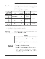
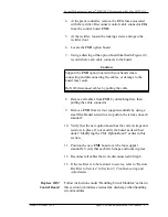
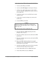
As described in schematic drawings SD-82605-01, replacement
CM1 option boards are supplied with all wire straps and
resistors in place. The same wire straps and resistors that were
removed from the original board must be removed from
replacement boards in order for the rectifier to operate properly.
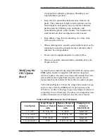
Table 8-B and Figure 2-2 show the straps and resistors to keep
and to remove from the CM1 board for each option on the
J85503A-1 rectifier. The plug-in type wire straps are removed
completely from a 2-hole jack. The other wire straps shown are
soldered in and are never replaced once they are removed.
Table 8-B: Modifications for the CM1 Board
List/Option
Keep Straps or
Resistors Marked
with
Remove Straps or
Resistors Marked
with
Stamping to be
Added on
ED-83159-30
1, 3, or 5
N, V, K, M
F, R, W
Mod AA
1, 3, or 5 and 17
N, V
F, R, W, K, M
Mod AB
2, 4, or 6
N, W, K, M
F, R, V
Mod AC
2, 4, or 6 and 17
N, W
F, R, V, K, M
Mod AD

