Lucent Technologies Lineage
®
2000 100A Ferroresonant Rectifier J85503A-1
Issue 6 October 1998
Installation 5 - 17
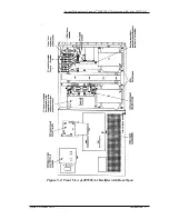
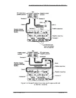
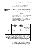
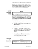
In Figure 5-4 rectifier wiring appears as in the lower drawing
before the work is started, and appears as in the upper drawing
upon completion of the work. Save the washers and nuts that are
removed for later use.
1. Remove both ends of Cable A from terminal B and
terminal C.
2. Remove the end of Cable C from terminal D. Reconnect
this end to terminal C.
3. Remove the end of Cable B from terminal A. Reconnect
this end to terminal B.
4. Install Cable A, removed in Step 1, between terminal A
and terminal D.
5. The wiring should now appear as in the upper drawing of
Figure 5-4. Indicate that the rectifier is now a negative
output (positive ground) system by removing the “List B”
stamping.
Initial Battery
Charging
(Optional)
Initial battery charging should be planned as part of the plant
installation. If initial battery charging is desired with the current
rectifier installation, the rectifier should be tested before
following this procedure (see Section 6, Testing).
The J85503A-1 rectifier is capable of supplying a new battery
string with its initial charge. Since the voltage levels
recommended by battery manufacturers for initial battery
charging are considerably above the normal plant voltage,
neither the battery nor the rectifier used to supply its initial
charge should be connected to the rest of the plant during this
procedure. One rectifier should be sufficient to supply the
charge. However, the high voltage shutdown levels must be
raised to accomplish the initial charge. The following procedure
describes how to raise the high voltage shutdown levels.
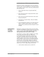
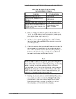
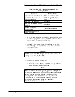
1. Set the rectifier controls as shown in Table 5-D.

